
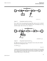

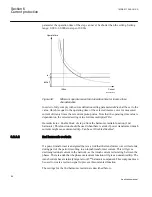
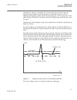


have instantaneous function. The overcurrent protection of IED A1 must have a delayed
function. The sequence of events during the fault can be described using a time axis, see
figure
.
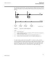
A1
B1
Feeder
Time axis
t=0
t=t
1
t=t
2
t=t
3
The fault
occurs
Protection
B1 trips
Breaker at
B1 opens
Protection
A1 resets
en05000205_ansi.vsd
51
51
ANSI05000205 V1 EN
Figure 39:
Sequence of events during fault
where:
t=0
is when the fault occurs
t=t
1
is when the trip signal from the overcurrent protection at IED B1 is sent to the circuit breaker. The
operation time of this protection is t
1
t=t
2
is when the circuit breaker at IED B1 opens. The circuit breaker opening time is t
2
- t
1
t=t
3
is when the overcurrent protection at IED A1 resets. The protection resetting time is t
3
- t
2
.
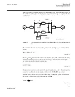
To ensure that the overcurrent protection at IED A1, is selective to the overcurrent
protection at IED B1, the minimum time difference must be larger than the time t
3
. There
are uncertainties in the values of protection operation time, breaker opening time and
protection resetting time. Therefore a safety margin has to be included. With normal
values the needed time difference can be calculated according to equation
1MRK 511 286-UUS A
Section 6
Current protection
101
Application manual
Summary of Contents for REC650 ANSI
Page 1: ...Relion 650 series Bay control REC650 ANSI Application manual...
Page 2: ......
Page 26: ...20...
Page 66: ...Section 3 1MRK 511 286 UUS A REC650 setting examples 60 Application manual...
Page 71: ...IED IED ANSI05000460 V2 EN 1MRK 511 286 UUS A Section 4 Analog inputs 65 Application manual...
Page 82: ...76...
Page 92: ...86...
Page 170: ...164...
Page 176: ...170...
Page 274: ...268...
Page 288: ...282...
Page 350: ...344...
Page 369: ...363...


