


33
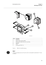
Making the electrical connections
Chapter 5
Installing the terminal
3
Making the electrical connections
Always make sure established guidelines for this type of terminal is followed during installation.
When necessary use screened twisted-pair cables to minimize susceptibility. Otherwise use any
kind of regular nonscreened tinned cable or equivalent.
When using screened cabling always use 360
°
full screen cable bushings to ensure screen cou-
pling. Ensure that all signals of a single circuit are in the same single cable. Avoid mixing current
and voltage measuring signals in the same cable. Also use separate cables for control and mea-
suring circuits.
3.1
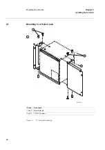
Connecting the CT circuits
CTs are connected using back-side mounted screw connectors.
Use a solid conductor with a cross section area between 2.5-6 mm
2
(AWG14-10) or a stranded
conductor with a cross section area between 2.5-4 mm
2
.
If the terminal is equipped with a test-switch of type RTXP 24 COMBIFLEX wires with 20 A
sockets must be used to connect the CT circuits.
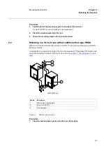
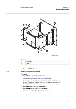
3.2
Connecting the auxiliary power, VT and signal connectors
Auxiliary power, VTs and signals are connected using COMBICON (Phoenix technology)
plug-in screw connectors.
Procedure
1.
Connect signals to the COMBICON plug.
2.
Plug the connector to the corresponding back-side mounted recept-
able.
3.
Lock the plug to the receptable by fastening the lock screws.
Use a solid or stranded conductor with a cross section area between
0.5-2.5 mm
2
(AWG20-14). Use a ferrule with plastic collar to connect
two conductors, cross section area between 0.5-1.5 mm
2
(AWG20-16).
Note!
Screened and twisted pair cables are a requirement for galvanic communications in application
with 56/64 kbit/s. The screen must be earthed according to figures in the sections “Making the
screen connection” and “Installing the communication cables”.
Summary of Contents for REB 551-C3*2.5
Page 9: ...Contents ...
Page 21: ...12 Introduction to the installation and commissioning manual Chapter 1 Introduction ...
Page 27: ...18 Note signs Chapter 2 Safety information ...
Page 53: ...44 Installing the 56 64 kbit data communication cables Chapter 5 Installing the terminal ...
Page 59: ...50 Checking the binary I O circuits Chapter 6 Checking the external circuitry ...
Page 147: ...138 Repair support Chapter 16 Fault tracing and repair ...