30
Mounting the terminal
Chapter 5
Installing the terminal
Procedure
1.
Cut the sealing strip in appropriate lengths.
The strip is delivered with the mounting kit. In the semi-flush mounting
kit two strips are delivered, one for the terminal and one self-adhering for
the distance frame. The length of the strip is enough for the largest avail-
able terminal.
Cut the strip into four, one part for each side of the terminal. When cut-
ting, make sure no gaps will be present between each part. Preferably,
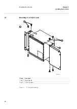
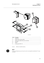
seal the joints at the corners (posNo 1).
Repeat the procedure for the self-adhering strip which are to be adhered
to the distance frame.
2.
Dispose the strip remains.
The remains should be source separated as soft plastic.
3.
Carefully press the cut strips into the front panel groove.
4.
Adhere the cut strips (posNo 3) to the edge of the distance frame
(posNo 2).
semi-flush mounting only.
5.
Make a panel cut-out.
See the Technical reference manual for cut-out dimensions.
6.
Insert the terminal into the cut-out.
7.
Add and lock the side holders (PosNo 4) to the terminal.
Thread a side holder into the groove (posNo 5) at the back end of the ter-
minal. Insert and lightly fasten the locking screw (posNo 6). Next, thread
a side holder on the other side of the terminal, and lightly fasten its lock-
ing screw.
Repeat this with the remaining two side holders.
8.
Lock the terminal to the cut-out.
Firmly tighten the locking screws. It is important that all four side holder
locking screws are tightened the same in order to maintain a good and
even seal in IP 54 environments.
2.4
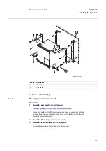
Mounting on a wall
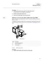
The mounting bars are prepared for adding DIN-rails or equivalent above and below the mount-
ed terminal. If used, make sure all necessary parts such as rails and terminal blocks are available
before starting. Make sure the wall mounting kit is available.
Summary of Contents for REB 551-C3*2.5
Page 9: ...Contents ...
Page 21: ...12 Introduction to the installation and commissioning manual Chapter 1 Introduction ...
Page 27: ...18 Note signs Chapter 2 Safety information ...
Page 53: ...44 Installing the 56 64 kbit data communication cables Chapter 5 Installing the terminal ...
Page 59: ...50 Checking the binary I O circuits Chapter 6 Checking the external circuitry ...
Page 147: ...138 Repair support Chapter 16 Fault tracing and repair ...

