


User-defined push buttons
3)
Connection to parallel inverter modules (if any)
4)
Main circuit
5)
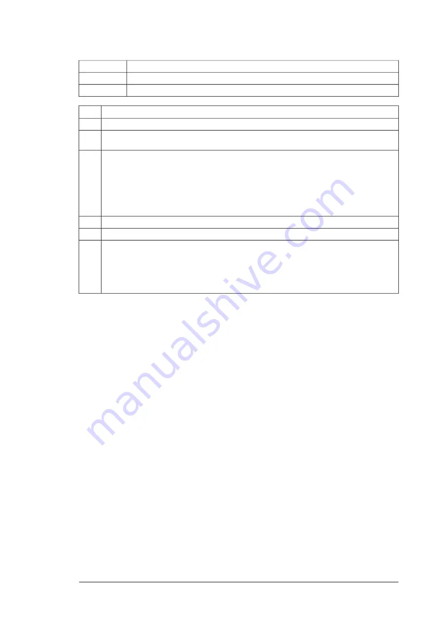
Operation
Step
Initial status: The drive is in operation and the motor is running.
The user pushes the emergency stop button [S61] or a user-defined push button. This activates the
emergency stop function.
1
The emergency stop safety relay [A61] de-energizes safety relays [K62.1] and [K62.2].
2
Safety relay [K62.2] de-energizes XSTO inputs IN1 and IN2 of the inverter control unit [A41]. This ac-
tivates the inverter unit Safe torque off function.
Safety relay [K62.2] de-energizes the DIIL input on the supply control unit [A51]. This gives the emer-
gency stop command to the supply unit.
Safety relay [K62.1] opens the main contactor/breaker [Qx], which disconnects the input power from
the supply unit [T01].
The emergency stop reset button indicator light [S62] comes on.
3
The motor coasts to a stop.
4
Normal operation resumes after the user:
5
•releases the emergency stop button [S61] or the user-defined button to normal (up) position
•pushes the emergency stop reset button [S62] to reset the emergency stop circuit
•resets the drive (if the drive tripped on a fault)
•makes sure that the drive receives the start signal (depends on the configuration, see the firmware
manual).
Description of Q951+Q984 19