background image

4NWP100559R0001_OPM_ABB_PVA31-11-T_10-20kVA_EN_140626

Page 24/37   ABB

Modifications reserved

5.2  Operating 

Mode

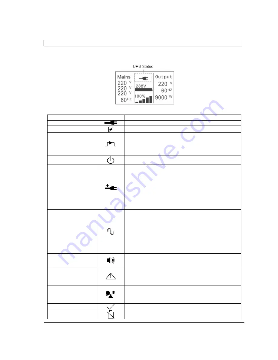
Different symbols indicate the status and the operating mode of the UPS. Such symbols appear always

in the position indicated in Figure 21.

Figure 21: Operating mode

Status

Symbol

Description

Online-mode

UPS is running through the inverter (Online-mode)

Battery-mode

UPS running on battery.

Bypass-mode

The power used by the load is supplied from the mains power via
internal filter.
Note that if there is a power failure and the UPS in on bypass, it
will not transfer back to mains or to battery-mode. (This only
happens if the UPS is in ECO-mode).

Stand-by-mode

UPS is running on bypass but there is no power in the output.

ECO-mode

After the UPS is turned on, the power used by the load is
supplied from the mains via internal filter if its power is in an
acceptable range. This guarantees higher efficiency of the UPS.
In case of mains failure, the UPS transfers to Online-mode or
Battery-mode and the load is supplied continuously.

Note

: ECO-mode can be enabled/disabled through the LCD

settings or through the monitoring software.

Warning

: The transfer time of UPS output from ECO-mode to

battery-mode is 10ms and not recommended for sensitive loads.

Converter-mode

In converter-mode, the UPS runs with fixed output frequency
(50Hz or 60Hz). In case of mains power failure, the UPS
transfers to battery-mode and the load is supplied continuously.

Note:

- Converter-mode function can be enabled/disabled through the
LCD settings or the monitoring software.
- The load should be de-rated to 60% in converter-mode with
single phase input. No de-rating is needed in three phase input
configuration.

Warning

Warnings indicate abnormal situations that do not stop the UPS
from working. In these cases, the UPS continues running but the
user should do corrective actions. See Section 7 for details.

Fault

In situations of failure, the UPS may disconnect the load or
transfer to bypass depending on the cause of the failure. In all
cases, there will be a constant alarm and the backlight of the
UPS will become red. See Section 7 for details.

Overload

When the UPS is in overload, unnecessary loads should be
disconnected one by one to decrease the load. The load should
be lower than 90% of its nominal power capacity in order to stop
alarming.

Battery test

UPS is performing a battery test.

Battery disconnected

The battery is disconnected or defective. The UPS alarm sounds.

Summary of Contents for PowerValue 31/11 T 10 kVA

Page 1: ...0001_OPM_ABB_PVA31 11 T_10 20kVA_EN_140626 Page 1 37 ABB Modifications reserved PowerValue 31 11 T 10 20 kVA User Manual 4NWP100559R0001_OPM_ABB_PVA31 11 T_10 20kVA_EN_140626 Copyright 2014 ABB All rights reserved ...

Page 2: ...4NWP100559R0001_OPM_ABB_PVA31 11 T_10 20kVA_EN_140626 Page 2 37 ABB Modifications reserved This page left intentionally blank ...

Page 3: ...mentals of electricity wiring electrical components and electrical schematic symbols THE INSTRUCTIONS IN THIS MANUAL SHOULD BE FOLLOWED DURING INSTALLATION OPERATION AND MAINTENANCE OF THE UPS AND BATTERIES Read carefully all instructions and save this manual for future reference SYMBOLS The following symbols are used in this manual the list below describes each symbol WARNING DANGER OF ELECTRICAL...

Page 4: ...very Transportation Positioning and Storage 11 4 1 1 Receipt of the UPS and visual inspection 11 4 1 2 Unpacking 11 4 1 3 UPS storage 12 4 1 4 Planning before the installation 12 4 2 Electrical Installation 12 4 2 1 Commissioning 12 4 2 2 Connections 13 4 3 Batteries 19 4 3 1 In built batteries 19 4 3 2 External battery cabinets 20 4 4 Backfeed Protection 20 4 5 Emergency Power Off EPO 21 4 6 Inst...

Page 5: ...etwork Management Card Optional 32 6 3 1 Installing a Serial Network Management Card optional 33 6 3 2 AS400 Dry Contact card 33 6 3 3 Monitoring Software 33 7 TROUBLESHOOTING 34 7 1 Fault identification and rectification 34 7 1 1 Troubleshooting without an error message 34 7 1 2 Troubleshooting based on error message 34 8 TECHNICAL SPECIFICATION 36 ...

Page 6: ...XT BEFORE STARTING WITH THE MAINTENANCE WORK ON THE CIRCUIT BREAKERS MAKE SURE THE UPS IS ISOLATED 1 2 Environmental Considerations To operate the UPS at the best efficiency point your installation site should meet the environmental parameters outlined in this manual Excessive amount of dust or moisture in the operating environment may cause damage or lead to malfunction The UPS should be always p...

Page 7: ...inquiries about the UPS to the local office or agent authorized by the supplier Please note the type code and the serial number of the equipment and contact your nearest agent authorized by the supplier The serial number is shown in the nameplate of the product For further information on troubleshooting go to Section 7 1 5 Operation Do not remove the enclosure of the UPS This system is to be servi...

Page 8: ...years at 25 C ambient temperature has been exceeded the batteries must be replaced In this case please contact your dealer The UPS should be charged once every 4 to 6 months if it has not been used for a long time The batteries charge to 90 capacity in approximately 4 hours However it is recommended that the batteries charge for 48 hours after long term storage In high temperature regions the batt...

Page 9: ...ew Figure 2 Front view of PowerValue 31 11 T 10 and 20 kVA 3 1 2 UPS rear view 10 kVA 20 kVA Figure 3 Rear view of PowerValue 31 11 T 10 and 20 kVA Number Description 1 LCD display 2 LEDs 3 Control keys 4 Ventilation inlets 5 Wheels 6 UPS support Number Description 1 Terminal blocks 2 Input breaker 3 Back feed control 4 Fans 5 Relay card slot 6 EPO contact 7 RS232 port 8 USB port 9 Parallel port 1...

Page 10: ...cabinet front view Figure 4 Front view of external battery cabinet 3 1 4 External battery cabinet rear view Figure 5 Rear view of external battery cabinet Number Description 1 Ventilation inlets 2 Wheels 3 UPS support Number Description 1 Ventilation inlets 2 Fuse holder 3 Connection terminals 4 Wheels 5 UPS support ...

Page 11: ... with a plastic sheet Preserve the packaging for later re use 4 1 2 Unpacking To unpack the unit follow the steps below 1 Using a forklift position the unit in the place where it will be installed The UPS has wheels that makes it easy to move be moved after unpacked but avoid dragging it long not to damage the wheels 2 Remove the caron box from the top of the unit 3 Remove the protection on the si...

Page 12: ...50 cm of space on each side of the cabinet to enable cooling airflow and ensure that the circulation of air to the ventilation slits is not obstructed Avoid excessively high temperature and excessive moisture Make sure that the surface is solid and flat Note that water condensing may occur if the UPS is unpacked in a very low temperature environment In this case it is necessary to wait until the U...

Page 13: ...2 5 mm2 Max section 4 mm2 Min section 6 mm2 Max section 10 mm2 Input breaker internal 40A 60A Mains 2 Input M2 N bypass Min section 10 mm2 Max section 13 mm2 Min section 21 mm2 Max section 25 mm2 Input breaker M2 bypass 63A 100A Battery Circuit breaker 40A 400V 80A 400V Output Output L N Min section 10 mm2 Max section 13 mm2 Min section 21 mm2 Max section 25 mm2 External Battery cabinet Positive N...

Page 14: ... UPS Note The terminal of the phase cable must have a ring connector in some configurations 11 configuration Single input feed Phase cable 11 configuration Dual input feed Phase cable 11 configuration Single input feed L3 phase cable Note If the UPS is used as a standalone UPS jumpers 1 and 2 must be connected If the UPSs are used in parallel configuration the jumper between JP1 and JP2 must be re...

Page 15: ...d internally to mains 1 For this there is no need to connect the neutral cable to the mains 1 terminal 2 Connect the 3 pole fork provided with the UPS between terminals L1 L2 and L3 Figure 7 3 pole fork installation 3 Connect the M2 cable provided with the UPS refer to section 4 2 2 1 between terminal M2 and the fork use the M5 screw provided in the fork connection 4 Connect the phase cable from t...

Page 16: ...served Dual Input Feed 1 Connect the neutral cables to the neutral terminals mains 1 and mains 2 2 Connect the 3 pole fork provided with the UPS between terminals L1 L2 and L3 Figure 9 3 pole fork installation 3 Connect the phase cables accordingly Figure 10 Dual feed 11 wiring diagram ...

Page 17: ...ith the UPS to terminal L3 Figure 11 1 pole fork installation 3 Connect the cable provided with the UPS between M2 and terminal L3 4 Connect the phase cables to the corresponding terminals Figure 12 Single feed 31 wiring diagram Dual Input Feed 1 Connect the neutral cable to the neutral terminal main 2 Note that the mains neutral is connected internally in the UPS Isolate and do not connect neutra...

Page 18: ... the parallel cable and re screw the parallel port cover supplied in the accessories 4 Disconnect the jumpers JP1 and JP2 on the terminal block and connect each output breaker to a main output breaker and then to the loads 5 Strictly follow the wiring requirement of single UPS to perform the wiring of each UPS Note that each UPS needs an independent battery pack Refer to section 4 2 2 1 and Figure...

Page 19: ...n series The nominal DC voltage of a battery block is therefore 288Vdc 4 3 1 In built batteries Some models of PowerValue 31 11 T have with interbal batteries These batteries are already installed and connected when the units are delivered To replace reduce or increase the amount of batteries connect the batteries as indicated in Figure 16 Connect the terminals to their matching color terminals 1x...

Page 20: ...kVA 3 50 A Table 2 Recommended fuse rating 3 Set the battery breaker to the position OFF and connect the batteries 24 batteries in series 4 Connect the battery cabinet to the battery terminals in the rear of the UPS 5 Reconnect the internal battery cables if present 6 Connect the input wires of the UPS and then set the battery breaker to the position ON The UPS will start charging the batteries 4 ...

Page 21: ...ally Opened NO through the USB or RS232 port Contact your local supplier for further information before modifying the settings 4 6 Installation Checklist All packing materials and restraints have been removed from each module Each module in the UPS system is placed in the installed location All conduits and cables are properly routed to the UPS and auxiliary enclosures All power cables are properl...

Page 22: ...ng start up Operation of additional SNMP adapters and their software 5 1 Control Panel The user friendly control panel is composed of LEDs an LCD display and four selection keys Figure 18 Control Panel 5 1 1 LEDs The LEDs gives the UPS mode or a faulty situation at a glance The LEDs may blink or stay constantly on depending on the UPS status Table 3 indicates the meaning of each LED UPS status LED...

Page 23: ...case of a critical alarm the backlight color changes to orange with dark text The buzzer also indicates different UPS status Figure 19 indicates the buzzer status meanings UPS condition Buzzer status Active failure Continuous Active warning Beep every second Battery output UPS on battery Beeps every 4 seconds Low battery buzzer beeps every second Bypass Beep every 2 minutes Overload Beep twice eve...

Page 24: ...ng software Warning The transfer time of UPS output from ECO mode to battery mode is 10ms and not recommended for sensitive loads Converter mode In converter mode the UPS runs with fixed output frequency 50Hz or 60Hz In case of mains power failure the UPS transfers to battery mode and the load is supplied continuously Note Converter mode function can be enabled disabled through the LCD settings or...

Page 25: ... 1 Check that all cables are connected correctly and well fixed mechanically 2 Check that the battery cabinet breaker is on position ON when using external battery cabinets 3 Press the power on button The UPS will perform a self test and display the status screen 4 Press the power on button continuously for more than 1s the alarm buzzer sounds and the UPS start up takes place 5 After a few seconds...

Page 26: ...ansfer to bypass automatically 4 Set the own maintenance switch of each UPS from UPS to BPS 5 Switch off the main output breaker and the main input breaker The UPS will shut down 6 Check that that there is no current in the output and that the UPS is switched off 7 Add the new UPS and reinstall the new UPS parallel system by following steps 1 7 of section 4 2 2 3 8 Switch on the main input breaker...

Page 27: ... and it will transfer automatically to online mode Note If the bypass is disabled in the settings menu when pressing the power on button for 3s the UPS goes from online mode to stand by mode 5 4 2 Navigation To navigate through the UPS screens the scroll buttons are used From the main screen UPS status screen press or for information on alarm and battery From the main screen press for more than 1s...

Page 28: ...ion Possible Values Default Values Buzzer mute Single UPS battery test Parallel UPS battery test Clear EPO status Reset failure status Clear event log Restore factory settings Mute the UPS sound Initiate test of the batteries of a single UPS Initiate test of the batteries of a group of UPSs Remove UPS from emergency power off status Reset warning and alarming status and buzzer Reset all the events...

Page 29: ...n menu Figure 24 Identification menu tree 5 4 2 5 User s Settings Some settings can impact on the performance of the UPS and others can enable and disable functions within the UPS Failures and reduced protection can occur if the equipment is not set in an adequate way Note that most settings should be done only with the UPS in bypass mode Press for less than 1s in the Settings menu to enter the su...

Page 30: ...g Power strategy Define the running mode to normal ECO mode or high efficiency and converter mode normal high efficiency ECO mode converter normal DC start Cold start Start the UPS from the batteries without mains power enabled disabled enabled Automatic battery tests period Define the frequency of the battery tests 0 31 days 7 days Auto restart After power outage the loads restart automatically w...

Page 31: ...bypass is above this limit the UPS changes running mode 1 10 5 Eco mode frequency low limit When the frequency in the bypass is below this limit the UPS changes running mode 1 10 5 Eco mode frequency high limit When the frequency in the bypass is above this limit the UPS changes running mode 1 10 5 External Battery modules Define the number of external battery modules 0 97 0 Set running time Used ...

Page 32: ...the serial communication cable that comes with the UPS to the RS 232 port on the UPS and the other end of the serial cable to the RS 232 port on a computer The cable pins for the RS 232 communication port are described in Figure 27 and in Table 7 Figure 27 RS 232 Communication Port DB 9 Connector Table 7 RS 232 Port Pin Assignment 6 2 USB port The UPS can communicate with an USB compliant computer...

Page 33: ... Cards see the SNMP User s Manual 6 3 2 AS400 Dry Contact card Alarm indication is possible through the AS400 potential free dry contact card The following is the pin assignment and description of DB 9 connector in AS400 card Figure 28 RS 232 Communication Port DB 9 Connector Pin Number Description I O 1 UPS Fail Output 2 Summary Alarm Output 3 GND Input 4 Remote Shutdown Input 5 Common Input 6 By...

Page 34: ...harge the batteries for at least 12 hours and then check capacity 7 1 2 Troubleshooting based on error message Message displayed Possible cause Remedy Inv Overload Failure Alarm code 42 Overload Check the loads and remove non critical loads Check if some loads have failures Byp Overload Failure Alarm code 43 Overload Check the loads and remove non critical loads Check if some loads have failures O...

Page 35: ...e UPS will go on bypass mode Parallel cable loss Alarm code E2 The parallel cable is disconnected Check the parallel cable Backfeed Alarm code 93 UPS internal fault Do not touch any terminal of the equipment even if the utility power has been cut off Contact UPS dealer Please collect the following information before calling the After Sales Service Department 1 Model number serial number 2 Date on ...

Page 36: ...capability linear load 5 min 105 110 1 min 110 130 10 s 130 150 2s 150 Nominal frequency 50 or 60 Hz 0 1 Hz Crest factor 3 1 EFFICIENCY AC AC Up to 93 In eco mode Up to 97 ENVIRONMENT Protection rating IP 20 Storage temperature 15 60 C for UPS 0 35 C for battery Operating temperature 0 40 C Relative humidity 0 95 Non condensing Altitude above sea level 1000m without de rating BATTERIES Type VRLA v...

Page 37: ...4NWP100559R0001_OPM_ABB_PVA31 11 T_10 20kVA_EN_140626 Page 37 37 ABB Modifications reserved ...

Reviews: