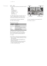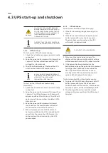
ESC
Online mode
Battery mode
Bypass mode
Fault
Escape
Up
Down Enter
On/Off
Battery Load
20
Min
100
%
Output
230 50
V
Hz
LED’s
Selection
keys
LCD
20
A B B U PS PRODUC TS A N D SOLUTI ON S
—
4 Operation
The user-friendly control panel has two parts:
• Selection keys
• Power management LCD (PMD)
• Status LEDs
—
4 .1 Control panel
This chapter describes how the UPS is operated
through the LCD.
The user can:
• Operate the LCD
• Start up and shut down the UPS (excluding the
commissioning start up)
• Operate additional SNMP/Modbus adapters
and their software
—
20 Control panel
4 .1 .1
Selection keys
—
Table 6: UPS selection keys
Button
Function Illustration
Power
ON/OFF
Turn the UPS on
and off or change
operating mode.
Scroll UP
Scroll up
through the menu.
Scroll DOWN
Scroll down
through the menu.
Select / Edit
Select and
confirm settings.
Exit / Mute
Exit menus and
mute the buzzer.
4 .1 .2
LED’s status indicators
—
Table 7: UPS selection keys
Indicator
Status
Description
NORMAL
(GREEN)
ON
The UPS is operating normally
on online or on high efficiency
mode.
BATTERY
(ORANGE)
ON
The UPS is in battery mode.
BYPASS
(ORANGE)
ON
The UPS is in bypass mode.
Flash
The UPS is in standby mode.
FAULT
(RED)
ON
The UPS has an
active alarm or fault.
—
20
Summary of Contents for PowerValue 11 T G2 10 kVA B
Page 41: ...41 APPENDIX B ...


