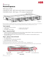


QUICK START GUIDE
Page 3
© 2021 ABB. All rights reserved.
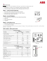
1.
Strip wire
1/2”
2.
Insert wire fully into wire entry
3.
Pull wire to verify insertion
Step 4
-
Verify DC Input Voltage and Polarity
•
Verify that the DC Input voltage is
-
48VDC and matches the marked polarity using a meter.
Note: Equipment will operate properly only with proper DC Input voltage and polarity.
DC Output Return Terminals
(
-
48V DC Return / Ground )
DC Output Terminals
(
-
48V DC)
Module 4
Module 3
Module 2
Module 1
Release hole (#0 Phillips or
1/8”
flat screw driver)
To Remove a wire:
Push the screw driver into release hole at a downward
angle. Pull the wire out of the terminal.
Wire Entry
24
-
8 gage
150036912
Negative (
-
48V)
Positive (ground)
150028529
Step 5
-
Connect DC Outputs
•
Connect DC Output and DC Output Return wires for each output.
32 DC Outputs
-
8 per Module.
Step 6
-
Connect Alarm Cable
1.
Remove alarm connector from the chassis.
2.
Connect alarm cable.
3.
Insert alarm connector into the chassis.
1. Strip wire
3/16”
2. Insert wire fully into wire entry
3. Tighten screw
Close On Alarm—COA
Open On Alarm—OOA
Common—
COM
Wire entry
28
—
16
gauge
Screw ( I/I6
”
flat screw driver
)
Alarm connector location —
typical


