ABB MRP31.0 Manual Download Page 4


Overview

This chapter contains a short description of the RS-485 standard and the MRP31.0 Modbus Interface module.

RS485 Standard

RS-485 is a serial interface standard for communication over a twisted-pair cable. Because the RS-485 signal transmission is 
differential, it provides better protection against noise and longer transmission distances than the RS-232. RS-485 is a 
half-duplex multi-drop network, which means that multiple devices may reside on line. Only one transmitter may be active at 
any given time. The RS-485 standard specifies only the electrical characteristics of the bus system.
The RS-485 transmission line consists of two wires, A and B. The signal transmission is based on the voltage difference 
between the wires. The potential difference between the two wires determines the logic state bit: when B is at higher 
voltage than A, the state is defined as bit 1 (data high) and when A is at higher voltage than B, the state is defined as bit 0 

(data low).
Ground wire and cable shield should be connected to prevent common mode voltage between the network devices from 

drifting outside the allowable limits. RS-485 bus cable should be terminated with a 120 Ohm resistor on both ends to 

prevent signal reflection.

The MRP31.0 Modbus Interface

The MRP31.0 Modbus communication interface is an optional device for the UMC100.3 which enables the connection of the 

UMC100.3 to a RS-485 network. The MRP31.0 provides galvanic isolation between the UMC100.3 and the RS-485 network.

• 

Use operator panel UMC100-PAN on UMC100.3 to set bus address, baud rate and timeout of the Modbus communication. 

Parity and frame length are automatically detected

•  MRP31.0 supports the RTU transmission mode only
• 

MRP31.0 is considered as a slave on the Modbus RTU network. Only one master can communicate with the MRP31.0 at a 

time.

Through the interface you can:

• 

Give control commands to the UMC100.3 (for example Start, Stop, Fault Reset)

•  Read status information and actual process values from the UMC100.3
•  Read device diagnosis information
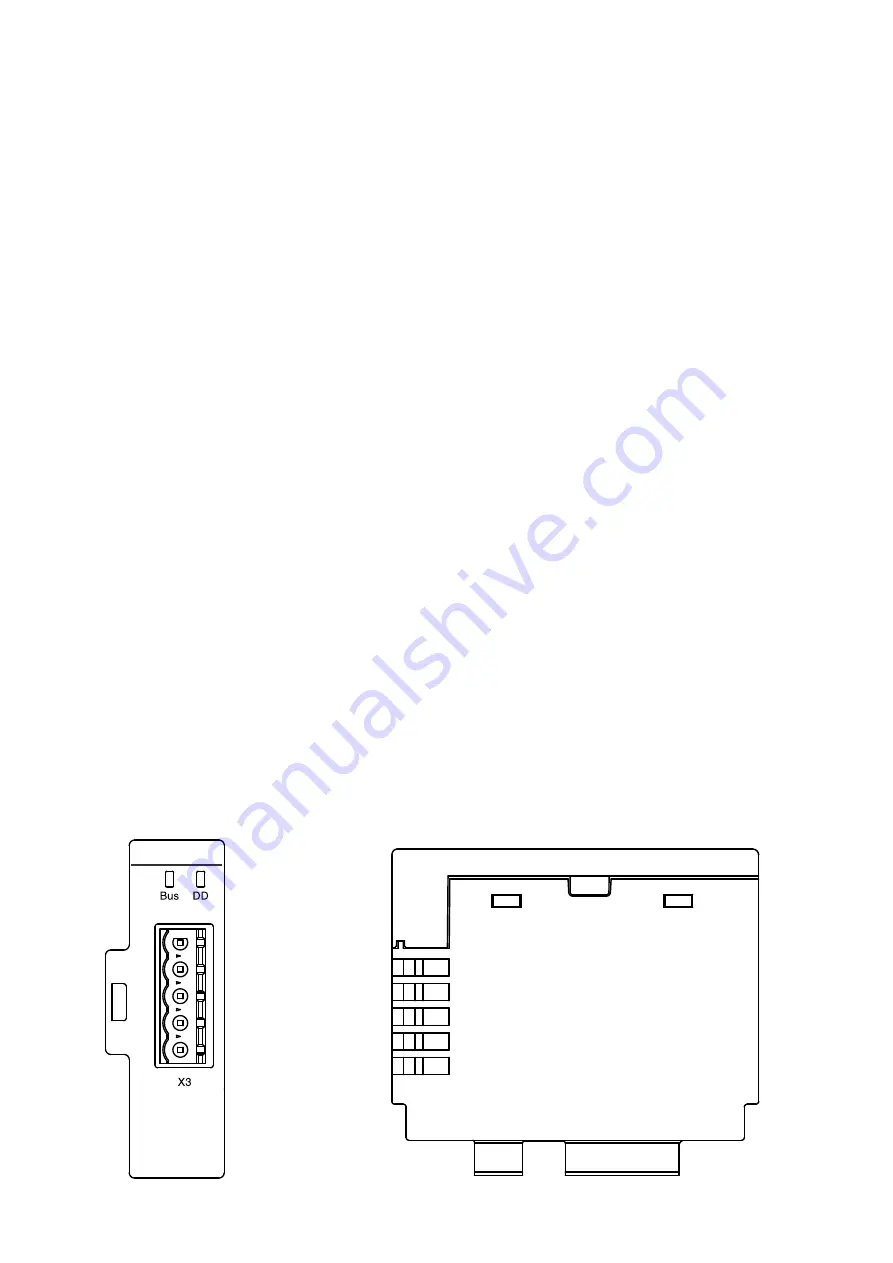
MRP31

X3:  
Modbus 
connection

Status Indication 
LEDs

X3: Modbus connection

X1: Communication  
to UMC100.3

X2: 24V DC 


supply connection

Top View

Side View

4

U N I V ER S A L  M OTO R  CO N T R O L L ER  U M C 10 0. 3  | 

M R P31 .0  MODBUS  TCP  COM M U N I C ATI ON  MODU LE  M A N UA L

Summary of Contents for MRP31.0

Page 1: ...MANUAL MRP31 0 Modbus RTU communication module Universal Motor Controller UMC100 3...

Page 2: ...ormation potential risks and precautionary information The following symbols are used Sign to indicate a potentially dangerous situation that can cause damage to the connected devices or the environme...

Page 3: ...4 Overview 5 Installation 11 Diagnosis 15 Technical data 16 Dimensional drawings 17 Ordering data 3 UNIVERSAL MOTOR CONTROLLER UMC100 3 MRP31 0 MODBUS TCP COMMUNICATION MODULE MANUAL Table of contents...

Page 4: ...common mode voltage between the network devices from drifting outside the allowable limits RS 485 bus cable should be terminated with a 120 Ohm resistor on both ends to prevent signal reflection The...

Page 5: ...31 Move down MRP31 until snapped in to fix MRP31 on UMC100 3 Mounting the MRP31 0 remote from the UMC100 3 When the communication interface is installed remote from the UMC100 3 e g in the cable chamb...

Page 6: ...nting the MRP31 0 on a 35 mm standard mounting rail Mounting the MRP31 0 on the single mounting kit Step 1 Plug in the communication and power supply connectors Step 3 Move down the MRP31 0 until snap...

Page 7: ...rocedure for demounting the MRP31 0 from UMC100 3 or SMK3 0 For demounting slightly rotate screw driver and move the MRP31 0 upwards to loosen snap in connection 7 UNIVERSAL MOTOR CONTROLLER UMC100 3...

Page 8: ...control panel UMC100 PAN plugged onto a UMC100 3 panel menu communication Modbus RTU and are copied then automatically to the MRP31 0 After changing communication settings perform a power cycle Maste...

Page 9: ...directly integrated in a Modbus TCP EtherNet network by using the MTQ22 FBP 0 interface Modbus line with MRP31 0 directly connected to UMC100 3 in a drawout system The following figure shows a simpli...

Page 10: ...ping of drawers detected if Address Check in UMC100 3 enabled I e it is not possible to accidentally start the wrong motor because of swapped drawer Required grounding of the Modbus cable is not shown...

Page 11: ...the maximum line length exceeded MODBUS parameters Is the baud rate correctly adjusted Is the MODBUS master in RTU mode Is the slave address correct Are there two devices with the same address in the...

Page 12: ...ILLEGAL FUNCTION The function code received in the request is not an allowable action for the slave It could also indicate that the slave is in the wrong state to process a request of this type for ex...

Page 13: ...ldbus Register Data 0x0200 Motor Current in of Ie 0 800 0x0201 Analog Word Thermal Load 0 100 0x0202 Analog Word Time to trip in seconds 0x0203 Analog Word Time to restart in seconds 0x0204 Analog Wor...

Page 14: ...se imbalance Phase loss Thermal overload trip Actuator problem UMC self test error Earth fault pre warning Earth fault trip internal or externally triggered I above high current warning threshold I ab...

Page 15: ...tion degree 3 Standards directives Product standard Modbus Specification RoHS directive 2011 65 EU Environmental data Ambient air temperature Operation 0 60 C Storage 25 70 C Vibration sinusoidal acc...

Page 16: ...X2 X1 Connection cables Pin Color Function 5 Blue VDD 4 Brown VCC 3 Black Communication 2 Grey Communication 1 White Diagnosis Colors must match Pin Function 2 24 V DC 1 0 V DC Drawer to UMC100 3 Dim...

Page 17: ...wer inside 1 5 m 1SAJ929240R0015 CDP24 150 Cable between SMK3 0 and drawer outside 1 5 m 1SAJ929610R0001 SMK3 X2 10 Terminal block 2 pol for SMK3 0 supply 10 pcs 1SAJ929620R0001 SMK3 X1 10 Terminal bl...

Page 18: ...egard to purchase orders the agreed particulars will take precedence ABB AG does not accept any responsibility whatsoever for potential errors or possible lack of information in this document We reser...

Reviews: