background image

Application note


Integrated Modbus support 

 AN00198 


ABB Motion control products 

11 

new.abb.com/motion 


MicroFlex e190 and MotiFlex e180 Modbus configuration 

MicroFlex e19

0 and MotiFlex e180 Modbus operation is configured via the ‘Configuration’ screens within Mint Workbench when 

online to the drive. All other products use Mint keywords to enable and configure Modbus Server operation. Download firmware 

from 

new.abb.com/motion

 or contact 

[email protected]

 to obtain the relevant Mint System File (.msx) to update a 

drive / motion controller. Note that Modbus support is only offered on Revision B e100 products (e.g. NXE100B-1608D

B

W). 


Configuration (Modbus TCP) 

All Modbus 

configuration for the MicroFlex e190 and MotiFlex e180 drives is performed via the ‘Configuration’ screens within 

Mint Workbench (these configuration settings can be saved as part of a controller archive to be transferred to another drive if 
necessary). Once online to the drive click on the ‘Configuration’ button in the Workbench Toolbox to display this work area. Note 
that for this screen to operate correctly the e190/e180 must have been ‘Discovered’ via the Mint HTTP Server (please refer to 
the MicroFlex e190 or MotiFlex e180 Installation Manual for further details about the operation of the Mint HTTP Server and the 

u

se of ‘Discovery’ to automatically scan and detect these devices). 

 
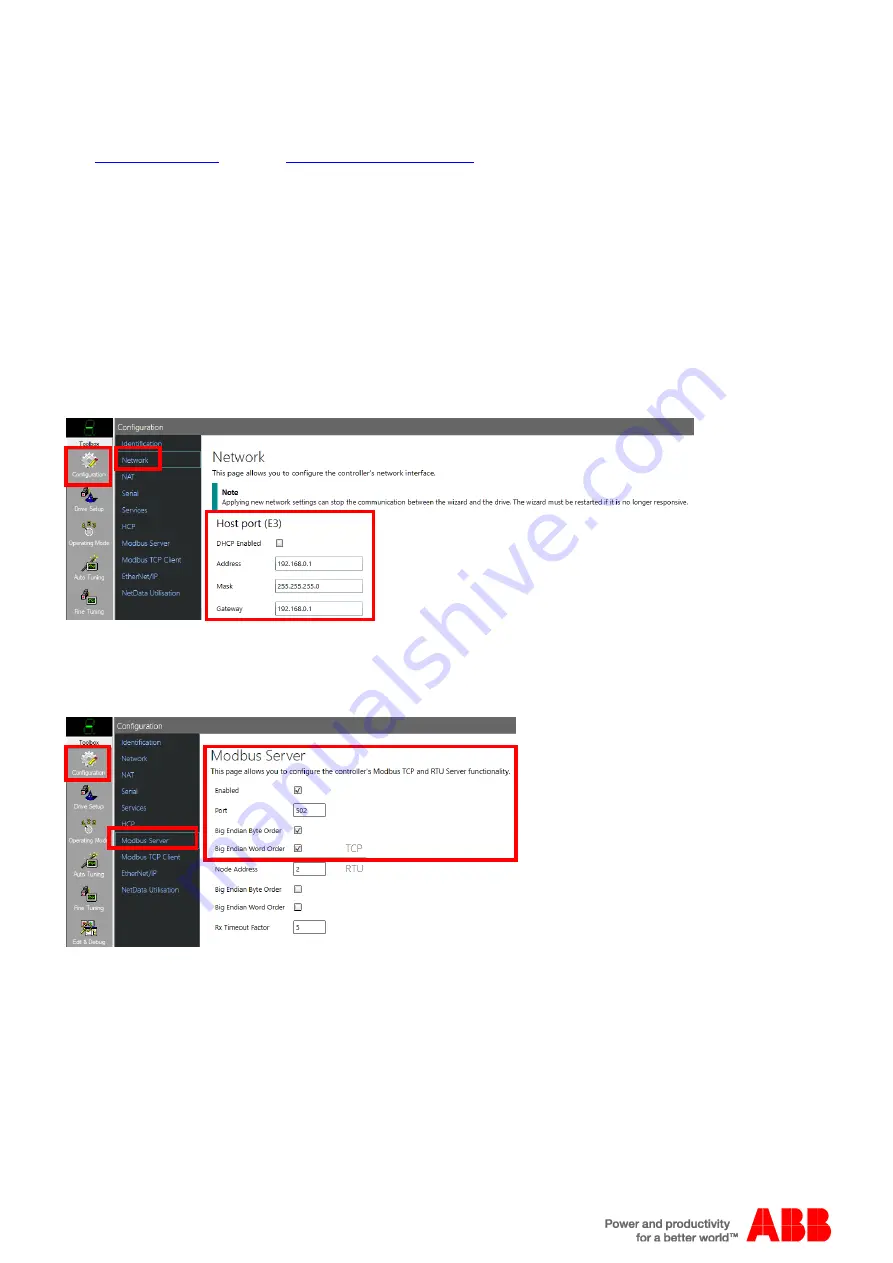
Click on ‘Network’ to configure the drive’s IP address (Modbus TCP uses the ‘Host port’ connection on the drive which is 
numbered E3)… 


The Gateway address must be on the same subnet as the drive (e.g. if the drive is 192.168.0.1 then the Gateway must be 

192.168.0.x where x is often just set to an unused address). 

Click on the ‘Apply’ button at the bottom of the screen to make any 

changes. 

Click on ‘Modbus TCP Server’ to configure Server operation… 


Check boxes are provided to enable/disable Server operation (enabled by default) and to configure the byte and word order of 

the Modbus data (set to Big Endian by default for compatibility with other ABB products supporting Modbus TCP operation). The 

standard Modbus port number is 502, but this can be changed if required to suit third party products using a custom port 

number. 

Summary of Contents for Modbus AN00198

Page 1: ...cal Client devices include host processors and programming panels Typical Servers include programmable controllers The Client can address individual Servers or can initiate a broadcast message to all Servers Servers return a message called a response to queries that are addressed to them individually Responses are not returned to broadcast queries from the Client The Modbus protocol establishes th...

Page 2: ... using RTU Remote Terminal Unit mode each 8 bit byte in a message contains two 4 bit hexadecimal characters Each message must be transmitted in a continuous stream The Mint interpreter offers support for Client devices with communication settings of 7 data bits 1 stop bit Even Parity 7 data bits 1 stop bit Odd Parity 8 data bits 1 stop bit No Parity Baud rates are limited to those supported by the...

Page 3: ...ponse For a normal response the Server simply echoes the original function code For an exception response the Server returns a code that is equivalent to the original function code with its most significant bit set to a logic 1 DATA n 8 bits NUL SOH NUL SOH The data field is constructed using sets of two hexadecimal digits in the range of 00 to FF hexadecimal that are then packed into a single ASC...

Page 4: ...mal In an exception response the Server sets the MSB of the function code to 1 This makes the function code value in an exception response exactly 80 hexadecimal higher than the value would be for a normal response With the function code s MSB set the Client s application program can recognize the exception response and can examine the data field for the exception code Data field In a normal respo...

Page 5: ...lement 1 LSW Element 1 Element 1 LSW Element 1 3 MW0 3 Element 1 MSW Element 1 MSW 4 MW0 4 MD0 2 Element 2 LSW Element 2 Element 2 LSW Element 2 5 MW0 5 Element 2 MSW Element 2 MSW 198 MW0 198 MD0 99 Element 99 LSW Element 99 Element 99 LSW Element 99 199 MW0 199 Element 99 MSW Element 99 MSW 200 MW0 200 MD0 100 Invalid Invalid Element 100 LSW Element 100 201 MW0 201 Invalid Element 100 MSW 202 MW...

Page 6: ...ducts Some third party Modbus products tend to use little endian word order so when using a third party Client it may be necessary to adjust this setting in the drive Modbus RTU and TCP are also supported as standard on the CP600 and CP600 eco ranges of HMI panels as well as the AC500 PLC range Network topology Modbus RTU When using 2 wire RS485 be sure to include 120 ohm terminating resistors bet...

Page 7: ...tween the switch and the devices see Application Note AN00247 for further details Note AC500 and CP600 products use a non standard RS232 pinout so be sure to check the relevant product manual before connecting other serial devices to these products Failure to observe the correct pinout may result in damage to the connected device Supported connection types Controller The table below shows the phys...

Page 8: ...n note Integrated Modbus support AN00198 ABB Motion control products 8 new abb com motion Example 1 Connect MotiFlex e180 Modbus TCP Client to MicroFlex e190 Modbus TCP Server via Switch or via crossover cable OR ...

Page 9: ...Example 2 Connect MicroFlex e190 equipped with OPT SIO 1 option card Modbus RTU Server to an external PLC e g AC500 COM2 Please refer to the OPT SIO 1 Option Card of MicroFlex e190 Servo Drive Quick installation guide for more information about how to install the option card AC500 COM2 e190 OPT SIO 1 ...

Page 10: ...lication note Integrated Modbus support AN00198 ABB Motion control products 10 new abb com motion Example 3 Connect MicroFlex e150 Modbus RTU Server to an external PLC e g AC500 eco AC500 eco COM2 e150 X6 ...

Page 11: ...n the Workbench Toolbox to display this work area Note that for this screen to operate correctly the e190 e180 must have been Discovered via the Mint HTTP Server please refer to the MicroFlex e190 or MotiFlex e180 Installation Manual for further details about the operation of the Mint HTTP Server and the use of Discovery to automatically scan and detect these devices Click on Network to configure ...

Page 12: ...cally add some default values as shown below These settings can be edited to suit the configuration of the connected Modbus TCP Server devices It is important to note the Server ID associated with the remote device this is automatically allocated and is one of the parameters used by the MODBUSTCPxx Mint keywords to read write data on the Server device so for example if Server ID 0 relates to 192 1...

Page 13: ...utton at the bottom of the screen to make any changes Configuration Modbus RTU Also the Modbus RTU configuration for the MicroFlex e190 drives is performed via the Configuration screens within Mint Workbench these configuration settings can be saved as part of a controller archive to be transferred to another drive if necessary Once online to the drive click on the Configuration button in the Work...

Page 14: ...CPFLOAT to access a single 32 bit floating point Modbus register are used Example 1 Client e180 wishes to take data from a local integer variable and write this to Netinteger 3 on a MicroFlex e190 via Modbus TCP The MicroFlex e190 has IP address 192 168 0 11 and is configured as Server ID 4 in the list of connected devices Dim nValue As Integer MODBUSTCP32 4 6 nValue Example 2 Client e180 wishes t...

Page 15: ...234 to NETFLOAT 1 on a remote MotiFlex e180 connected via Modbus TCP The MotiFlex e180 has IP address 192 168 0 2 and is configured as Server ID 0 in the list of connected devices MODBUSTCPFLOAT 0 2 1 234 When the MicroFlex e190 or MotiFlex e180 drive is operating as a Modbus Server Netdata events will only be raised whenever the Modbus Client writes modified data to Netinteger Netfloat locations ...

Page 16: ... motion The Client diagnostics page lets the user initiate a Read holding registers Modbus TCP function function code 03 Diagnostics about the transaction are displayed after clicking the Send button This allows the user to test basic Modbus TCP operation without the need to write any Mint code ...

Page 17: ... RTU parameters Mint pre defined constant values for index are _mpENABLE 0 0 Disabled 1 Enabled _mpREGISTER_MAPPING 1 0 NetData array e100 default 1 Comms array ESB 2 default _mpBYTE_ORDER 2 0 Big Endian default 1 Little Endian _mpWORD_ORDER 3 0 Big Endian default 1 Little Endian _mpDROPPED_FRAMES 6 Read only counter of number of invalid packets received _mpDEBUG 7 Parameter used to display Modbus...

Page 18: ... Protocol BBP functionality on the serial port Enabling Modbus RTU also prevents the controller from directing data from Mint PRINT statements to the serial port to avoid corruption of Modbus data packets Example Mint Code The following code snippets show typical Mint code that may be included in a NextMove controller s Startup block Example Mint code Mint Modbus RTU Server e g NextMove ESB 2 conn...

Page 19: ...response has been generated 2 Writing a terminal channel value to ModbusParameter bus _mpDEBUG will reset diagnostic counters and setup which terminal channel is to be used to display diagnostic information Reading ModbusParameter bus _mpDEBUG will then return which terminal channel is being used for diagnostics and will display some summary information on the selected terminal channel e g last pa...

Reviews: