


41-133S
10
Directional Overcurrent Ground Relays
Types IRP, IRC and IRD
tion indicator target should drop freely bringing the
letter “I” into view.
7.5.1 Auxiliary Switch (CS-1 or TR-1)
Adjust the stationary core of the CS-1 switch for a
clearance between the stationary core and the mov-
ing core when the switch is picked up. This can be
done by turning the relay upside-down. Then screw
up the core screw until the moving core starts rotat-
ing. Now back off the core screw until the moving
core stops rotating. This indicates the points where
the play in the assembly is taken up, and where the
moving core just separates from the stationary core
screw. Back off the core screw approximately one
turn and lock in place. This prevents the moving core
from striking and sticking to the stationary core
because of residual magnetism. Adjust the contact
clearance for 3/64” by means of the two small nuts
on either side of the Micarta disc. The TR-1 switch
does not require adjustment.
Connect lead (A) to proper terminal per Figure 26
(page 40). Block directional unit (D) contacts close
and energize trip circuit with rated voltage. Contacts
of auxiliary switch (CS-1 or TR-1) should make as
indicated by a neon lamp in the contact circuit.
8.0 RENEWAL PARTS
Repair work can be done most satisfactorily at the
factory. However, interchangeable parts can be fur-
nished to the customers who are equipped for doing
repair work. When ordering parts, always give the
complete nameplate data.
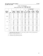
RELAY TYPE
TIME-OVERCURRENT
AMPERE RATING OF
UNIT
VALUES FOR
†
MIN. PICKUP
PHASE ANGLE RELATIONSHIP
VOLTS AMPERES
IRP (Voltage
IRD Unit)
IRC (Current
IRD Unit
)
∆
.5-2.5
2-6
4-12
.5-2.5
2-6
4-12
1
1
1
1
2.0
4.0
4.0
8.0
0.5
.57
1.0
1.3
l lagging V by 60
°
††
l in-phase with V
l lagging V by 60
°
††
l in-phase with V
lo leading lp by 40
°
††
In-phase
lo leading lp by 40
°
††
In-phase
†
The energization quantities are input quantities at the relay terminals.
††
Maximum torque angle.
∆
When normal system conditions limit the current to less twice pickup, performance may be
by selecting a higher current ct tap to energize the polarizing circuit.
TABLE
1
DIRECTIONAL UNIT SENSITIVITY
9.0 LIST OF FIGURES


