background image

ABB STOTZ-KONTAKT GmbH

Eppelheimer Straße 82, 69123 Heidelberg, Germany

Postfach 10 16 80, 69006 Heidelberg, Germany

+

 +49 (0) 6221 701 607

ª

 +49 (0) 6221 701 724

www.abb.de/stotz-kontakt

Technische Hotline / Technical Support:

+

 +49 (0) 6221 701 434

E-Mail: [email protected]

Summary of Contents for i-bus EIB RC/A 8.1

Page 1: ... drift RC A 8 1 Raum Controller Grundgerät für 8 Module AP Room Controller Basis Device for 8 Modules SM Contrôleur intérieur appareil de base pour 8 modules AP Ruimtecontroller basiseenheid voor 8 modules AP Unità di controllo spazio apparecchio di base per 8 moduli AP Controlador de sala unidad base para 8 módulos AP Rumsstyrenhet basenhet för 8 moduler utanpåliggande ABB i bus EIB GH Q660 7001 ...

Page 2: ...1 ...

Page 3: ...2 ...

Page 4: ...3 ...

Page 5: ...4 5 4 ...

Page 6: ...Ausfall der 115 230 V AC Versorgung bleibt so die Gerätefunktion vollständig erhalten 4 Zusatz Einspeisung Einige Module z B 24 V DC Jalousieaktor benötigen eine gesonderte Einspeisung die direkt an die Module angeschlossen wird Zur Erleichte rung der Verdrahtung können hier 24 V DC angeschlossen werden Klem men 5 6 die über eine mitgelieferte Brücke über die Klemmen 9 10 direkt auf die Module wei...

Page 7: ... der Module siehe obere Abbildung 1 Raum Controller Grundgerät spannungsfrei schalten 2 Schutzfolie von den Steuerleitungs Kontaktflächen entfernen 3 Einstecken des Gerätes und Kontaktierung der Einspeisung 4 Einrasten Entfernen der Module siehe untere Abbildung 1 Raum Controller Grundgerät spannungsfrei schalten 2 Mit Schraubendreher ausrasten 3 Gerät leicht anheben und von der Einspeise Kontakti...

Page 8: ... in der Zwischendecke Die Handbedienung erlaubt sofort nach Zu schalten der Spannung die Überprüfung der Modulfunktion und der Verdrahtung auch im unprogrammierten Zustand Das Gerät kann seine interne Versorgung neben der Einspeisung zusätzlich über eine 12 V DC Hilfsversorgung sicherstellen Dadurch kann das Gerät auch bei Ausfall der Einspeisung weiter funktionieren Bei Busspannungsausfall bleibe...

Page 9: ... und Anzeigeelemente LED rot und Taste zur Vergabe der physikalischen Adresse 4 LED s gelb und Taster zur Statusanzeige und Handbedienung der Modulfunktion 1 Drehwahlschalter zur Auswahl des zu bedienenden Modulplatzes Anschlüsse Hauptversorgung Einspeisung 5 polige steckbare Schraubklemme EIB 2 polige steckbare Schraubklemme Zusatz Einspeisung 3x2 polige steckbare Schraubklemme optionale Hilfsver...

Page 10: ...technischen Daten und dem Produkt Handbuch des Gerätes Diese Dokumente finden Sie zum Download im Internet unter http www abb de stotz kontakt Reinigen Verschmutzte Geräte können mit einem trockenen Tuch gereinigt werden Reicht dies nicht aus kann ein mit Seifenlösung leicht angefeuchtetes Tuch benutzt werden Auf keinen Fall dürfen ätzende Mittel oder Lösungsmittel ver wendet werden Wartung Das Ge...

Page 11: ... aus dem Raum Controller Grundgerät vor dem Abziehen von Steckklemmen während Anschluss der Ausgänge Bei der Planung und Errichtung von elektrischen Anlagen sind die einschlägi gen Normen Richtlinien Vorschriften und Bestimmungen zu beachten Gerät bei Transport Lagerung und im Betrieb vor Feuchtigkeit Schmutz und Beschädigung schützen Gerät nur innerhalb der spezifizierten technischen Daten betrei...

Page 12: ...n this way the device continues to function normally on the failure of the 115 230 V AC supply 4 Additional input voltage Some modules e g 24 V DC shutter actuator require a special input volt age that is connected directly to the modules To make the wiring easier 24 V DC can be connected here terminals 5 6 this is supplied direct to the modules via terminals 9 10 using a jumper supplied Terminals...

Page 13: ...tallation of the modules See top figure 1 Removing the Room Controller Basis Device from voltage 2 Removing the protection film for the mating surfaces of the control lines 3 Plug in of the device and contacting with the input voltage 4 Snapping in Removing the modules See bottom figure 1 Removing the Room Controller Basis Device from voltage 2 Unlocking with a screwdriver 3 Lifting the device sli...

Page 14: ...ts immediate checking of the module function and wiring as soon as the supply voltage is connected even in the unprogrammed state The device safeguards its internal power supply with a 12 V DC auxiliary power supply in addition to the input voltage In this way the device can con tinue to operate on the failure of the input voltage If the bus power supply fails the internal device functions continu...

Page 15: ...tton For assigning the physical address 4 yellow LEDs and buttons For status indication and manual operation of the module function 1 rotary selector switch For the selection of the module slot to be operated Connections Main power supply input voltage 5 pole plug in screw type terminal EIB 2 pole plug in screw type terminal Additional input voltage 3x2 pole plug in screw type terminal Optional au...

Page 16: ...ound in the technical data and in the product manual This information can be downloaded from the Internet site http www abb de stotz kontakt Cleaning Should the device become soiled it may be cleaned with a dry cloth If this does not suffice a cloth lightly moistened with soap solution may be used On no account should caustic agents or solvents be used Maintenance The device is maintenance free Sh...

Page 17: ...al from the Room Controller Basis Device Prior to pulling off the plug in screw type terminals During the connection of the outputs The relevant standards directives regulations and instructions must be ob served when planning and implementing the electrical installation Protect the device against moisture dirt and damage during transport storage and operation Do not operate the device outside the...

Page 18: ...limentation de 115 230 V AC le fonctionnement de l appareil peut être poursuivi sans interruption 4 Alimentation supplémentaire Certains modules comme le module d actionnement de stores de 24 V DC requièrent une alimentation séparée raccordée directement aux mo dules en question Ainsi pour alléger les câblages 24 V DC peuvent être directement raccordés bornes 5 6 aux modules par le biais d un pont...

Page 19: ...modules Voir l illustration ci dessus 1 Débrancher l appareil de base du contrôleur intérieur 2 Retirer le film de protection des surfaces de contact des câbles de com mande 3 Brancher l appareil et enclencher l alimentation 4 Encliqueter Démontage des modules Voir l illustration ci dessous 1 Débrancher l appareil de base du contrôleur intérieur 2 Dégager à l aide d un tournevis 3 Soulever légèrem...

Page 20: ...Dès la mise sous tension l actionnement manuel permet égale ment de contrôler le fonctionnement des modules ainsi que le câblage même sans programmation En plus de l alimentation générale une alimentation secondaire de 12 V DC peut également être mise à disposition de l appareil pour son alimentation in terne Ainsi l appareil peut continuer de fonctionner même en cas de panne de l alimentation gén...

Page 21: ...l type de module Eléments de réglage et d affichage DEL rouge et touche Pour indiquer l adresse physique 4 DEL jaunes et touche Pour indiquer le statut et l actionnement manuel des fonctions du module 1 commutateur rotatif Pour choisir l emplacement de module à utiliser Connexions Alimentation principale Borne à vis enfichable à 5 pôles EIB Borne à vis enfichable à 2 pôles Alimentation supplémenta...

Page 22: ... et de la mise en ser vice dans la documentation technique de l appareil Vous pouvez télécharger celle ci sur Internet sur le site www abb de stotz kontakt Nettoyage Les appareils sales peuvent être nettoyés à l aide d un chiffon sec Si cela ne suffit pas un chiffon légèrement imprégné de solution savonneuse peut être utilisé N utiliser en aucun cas des produits caustiques ou des solvants Entretie...

Page 23: ...térieur avant le débranchement des bornes à vis pendant le raccordement des sorties Les normes directives règlements et dispositions en vigueur doivent être res pectés lors de la planification et de la mise en place d installations électriques Protéger l appareil de l humidité de la saleté et de tout dommage lors du transport du stockage et de l utilisation N utiliser l appareil que dans le cadre ...

Page 24: ...minderd werken ook wanneer de 115 230 V AC voeding uitvalt 4 Aanvullende voeding Enkele modules bijv 24 V DC jaloezie actuator hebben een aparte voeding nodig die direct op de module wordt aangesloten Om de bedrading te vergemakkelijken kan hier 24 V DC worden aangesloten klemmen 5 6 die via een meegeleverde brug via de klemmen 9 10 direct naar de modules wordt geleid Klemmen 7 8 dienen voor het d...

Page 25: ...tallatie van de modules zie bovenste afbeelding 1 Ruimtecontroller basiseenheid spanningsvrij schakelen 2 Afschermfolie van de contactvlakken van de stuurleidingen verwijderen 3 Apparaat bevestigen en voedingsspanning contacteren 4 Vastklikken Verwijderen van de modules zie onderste afbeelding 1 Ruimtecontroller basiseenheid spanningsvrij schakelen 2 Met schroevendraaier losklikken 3 Apparaat stuk...

Page 26: ...e vloer of in een verlaagd plafond worden gemonteerd Met de handmatige bediening kunnen direct na aansluiting van de voedingsspanning de modulefunctie en de bedrading worden gecontroleerd ook in ongeprogrammeerde staat De interne stroomvoorziening van het apparaat kan behalve door de externe voeding worden gewaarborgd door een hulpspanning van 12 V DC Daardoor blijft het apparaat ook werken als de...

Page 27: ...estiging van willekeurig moduletype Bedienings en display elementen LED rood en toets voor toekenning van fysiek adres 4 LED s geel en drukknop voor statusweergave en handmatige bediening van modulefunctie 1 draaischakelaar voor het selecteren van modulelocatie Aansluitingen Hoofdvoeding 5 polige insteek schroefklem EIB 2 polige insteek schroefklem Aanvullende voeding 3x2 polige insteek schroefkle...

Page 28: ...che gegevens en het Producthandboek van het apparaat Deze documenten kunt u downloaden van het internet via http www abb de stotz kontakt Reinigen Verontreinigde apparaten kunnen worden gereinigd met een droge doek Wan neer dit niet toereikend is kan een licht met zeepsop bevochtigde doek wor den gebruikt In geen geval mogen bijtende middelen of oplosmiddelen wor den gebruikt Onderhoud Het apparaa...

Page 29: ...controller basiseenheid voordat de steekklemmen worden verwijderd tijdens het aansluiten van de uitgangen Bij het plannen en installeren van elektrische installaties dienen de des betreffende normen richtlijnen voorschriften en bepalingen te worden opgevolgd Apparaat tijdens transport opslag en bedrijf beschermen tegen vocht vuil en beschadiging Apparaat uitsluitend in bedrijf stellen volgens de g...

Page 30: ... 230 V il funzionamento dell apparecchio viene quindi mantenu to completamente 4 Tensione di ingresso aggiuntiva Alcuni moduli per es i dispositivi schermatori da 24 V CC necessitano di una tensione di ingresso a parte che viene collegata direttamente ai mo duli Per facilitare il cablaggio è possibile collegare qui 24 V di CC morsetti 5 6 che vengono poi condotti direttamente ai moduli tramite un ...

Page 31: ...nettere l apparecchio di base dell unità di controllo spazio dalla tensione 2 Rimuovere la pellicola protettiva dalle superfici di contatto delle linee di comando 3 Inserire l apparecchio e i contatti della tensione di ingresso 4 Innestare Rimozione dei moduli vedere figura sottostante 1 Disconnettere l apparecchio di base dell unità di controllo spazio dalla tensione 2 Sganciare con un cacciavite...

Page 32: ...intraparetale Il comando manuale permette subito dopo l attivazione della tensione la verifica della funzione dei moduli e il cablaggio anche in caso di assenza di programmazione L apparecchio può garantire la sua alimentazione interna oltre alla tensione di ingresso anche tramite un alimentazione ausiliaria CC a 12 V In questo modo l apparecchio può continuare a funzionare anche in caso di mancan...

Page 33: ...sto per l assegnazione dell indirizzo fisico 4 LED gialli e tasti per la visualizzazione dello stato e il comando manuale delle funzioni dei moduli 1 selettore a disco per la selezione del posto del modulo da comandare Collegamenti Alimentazione principale tensione di ingresso Morsetto a vite innestabile a 5 poli EIB Morsetto a vite innestabile a 2 poli Tensione di ingresso aggiuntiva Morsetto a v...

Page 34: ...nfigurazione dei parametri e la messa in servizio vedere i dati tecnici e il manuale dell apparecchio Questi documenti possono essere scaricati da Internet all indirizzo http www abb de stotz kontakt Pulizia Gli apparecchi sporchi possono essere puliti con un panno asciutto In caso risultasse insufficiente è possibile utilizzare un panno leggermente inumidito con una soluzione di sapone Non utiliz...

Page 35: ...aggio dall apparecchio di base dell unità di controllo spazio prima di staccare il morsetto a inserzione durante il collegamento delle uscite In fase di pianificazione e attuazione di impianti elettrici osservare le relative norme disposizioni direttive e istruzioni Proteggere l apparecchio durante il trasporto la conservazione e il funzionamento da umidità sporcizia e danneggiamenti Utilizzare l ...

Page 36: ...230 V CA el dispositivo seguirá funcionando correctamente 4 Alimentación adicional Algunos módulos por ejemplo el actuador para persianas 24 V CC necesitan una alimentación especial que se conecta directamente al módulo Para aligerar el cableado pueden conectarse 24 V CC bornes 5 6 que se llevan directamente al módulo a través de los bornes 9 10 con un puente incluido Los bornes 7 8 sirven para el...

Page 37: ... figura superior 1 Desenchufe la unidad base del controlador de sala de la toma de corriente 2 Retire la lámina protectora de las superficies de contacto de las líneas d e mando 3 Enchufe el dispositivo y conéctelo a la alimentación 4 Introdúzcalo Retirada de los módulos Véase figura inferior 1 Desenchufe la unidad base del controlador de sala de la toma de corriente 2 Extráigala con un destornill...

Page 38: ...lización manual permite comprobar la función del módulo y el cableado incluso en modo no programado al enchufarlo Además de la alimentación el suministro interno del dispositivo está garantizado mediante un suministro auxiliar adicional de 12 V CC Gracias a este suministro el dispositivo seguirá funcionando aún en el caso de que la alimentación falle En caso de que se produzca una avería en la ten...

Page 39: ...cla para otorgar la dirección física 4 LEDs amarillos y tecla para indicar el estado y para utilizar manualmente las funciones del módulo 1 selector de programas para seleccionar la posición del módulo que se ha de utilizar Conexiones Suministro principal Alimentación Bornes roscados de enchufe de 5 polos EIB Bornes roscados de enchufe de 2 polos Alimentación adicional Bornes roscados de enchufe d...

Page 40: ...formación detallada sobre la configuración y la puesta en funcionamiento Podrá acceder a estos documentos descargándolos desde la página web http www abb de stotz kontakt Limpieza Los dispositivos sucios pueden limpiarse con una toalla seca Si no es suficiente podrá utilizarse una toalla humedecida en una solución jabonosa No se podrán utilizar en ningún caso productos o disolventes corrosivos Man...

Page 41: ... unidad base del controlador Antes de retirar los bornes de enchufe Durante la conexión de las salidas Cuando se proyecten y se instalen dispositivos eléctricos deberán observarse en todo momento las normativas directivas y normas correspondientes Proteja el dispositivo de humedad suciedad y de posibles daños siempre que se transporte se almacene o cuando esté en funcionamiento Observe en todo mom...

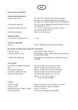
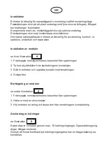
Page 42: ...ning Vid avbrott i 115 230 V AC försörjningen upprätthålls därmed enhetens funktion helt och hållet 4 Tilläggsinmatning Några moduler t ex 24 DC jalusiaktor kräver en separat inmatning som ansluts direkt på modulen För att underlätta dragningen kan 24 V DC anslutas här klämmor 5 6 som förs vidare direkt till modulen via en bifo gad brygga genom klämmorna 9 10 Klämmorna 7 8 används för vidare förbi...

Page 43: ...ler se övre illustration 1 Frånkoppla rumsstyrenhetens basenhet från spänningen 2 Ta bort skyddsfolien från styrledningens kontaktytor 3 Sätt in enheten och upprätta kontakt med inmatningen 4 Snäpp fast Borttagning av moduler se nedre illustration 1 Frånkoppla rumsstyrenhetens basenhet från spänningen 2 Haka ur med en skruvmejsel 3 Höj enheten en aning och lossa den från inmatningens kontaktering ...

Page 44: ... golv eller i trossbot ten Direkt efter att spänningen kopplats in går det att med den manuella manövreringen kontrollera modulfunktionen och dragningen även i oprogrammerat tillstånd Förutom via inmatningen kan enheten även säkerställa den interna försörj ningen via en 12 V DC hjälpförsörjning Enheten kan därmed fortsätta att fung era även vid ett avbrott i inmatningen Vid busspänningsavbrott bib...

Page 45: ...ingselement Lysdiod röd och knapp för tilldelning av fysikalisk adress 4 lysdioder gula och tryckknapp för statusindikering och manuell manövrering av modulfunktion 1 vred för val av den modulplats som ska manövreras Anslutningar Huvudförsörjning inmatning 5 polig insticksbar skruvklämma EIB 2 polig insticksbar skruvklämma Tilläggsinmatning 3 x 2 polig insticksbar skruvklämma Extra hjälpförsörjnin...

Page 46: ...ttagning finns under tekniska data och i enhetens produkthandbok Dessa dokument finns för nedladdning på Internet under http www abb de stotz kontakt Rengöring Nedsmutsade enheter kan rengöras med en torr trasa Om det inte är tillräckligt kan en trasa lätt fuktad med en tvållösning användas Frätande medel eller lösningsmedel får absolut inte användas Underhåll Enheten är underhållsfri Vid skador t...

Page 47: ...tyrenhetens basenhet innan borttagning av insticksklämmor under anslutning av utgångar Vid planering och installation av elektriska anläggningar ska tillämpliga standarder direktiv föreskrifter och bestämmelser följas Enheten ska skyddas mot fukt smuts och skador under transport och förvaring samt när den är i drift Enheten får endast användas inom specificerade tekniska data Enheten får endast an...

Page 48: ...eimer Straße 82 69123 Heidelberg Germany Postfach 10 16 80 69006 Heidelberg Germany 49 0 6221 701 607 ª 49 0 6221 701 724 www abb de stotz kontakt Technische Hotline Technical Support 49 0 6221 701 434 E Mail eib hotline de abb com ...

Reviews: