


ProcessMaster FEP610, HygienicMaster FEH610
| OI/FEP610/FEH610-EN Rev. B 17
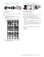
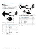
5.1.13
Installation in pipelines with larger nominal
diameters
Fig. 19: using reduction pieces
1
Transition piece
Determine the resulting pressure loss when using transition
pieces:
1. Calculate the diameter ratio d/D.
2. Determine the flow velocity based on the flow range
nomograph (Fig. 20).
3. Read the pressure drop on the Y-axis in Fig. 20.
Fig. 20: Nomograph for pressure drop calculations for flange
transition piece with α/2 = 8°
5.1.14
Installation in 3A-compliant installations
Fig. 21: 3A-compliant installation
1
Mounting bracket
2
Leakage hole
Please observe the following points:
A
Do not install the device horizontally with the terminal box
or transmitter housing pointing downward.
B
The "mounting bracket" option is not 3A-compliant.
C
Please ensure that the leakage hole of the process
connection is located at the deepest point of the installed
device.
— Prefer vertical installation. With horizontal installation make
sure the sensor is self-drainable
— Make sure the sensor terminal compartment cover and/or
the transmitter housing cover is tightened properly to
ensure there is no gap between the base of the housing
and the cover.
Only devices with following process connections are 3A-
compliant:
— Welded
stubs
— Tri-Clamp
G12014
D
d
8°
1
G12015
100
10
1
v=8 m/s
7 m/s
6 m/s
5 m/s
4 m/s
3 m/s
2 m/s
1 m/s
d/D
[mbar]
0,5
0,6
0,7
0,8
0,9
G12016
1
2
A
B
C


