ABB AB JOKAB SAFETY, Varlabersvägen 11, SE-43439 Kungsbacka
www.abb.com/lowvoltage
Original instructions
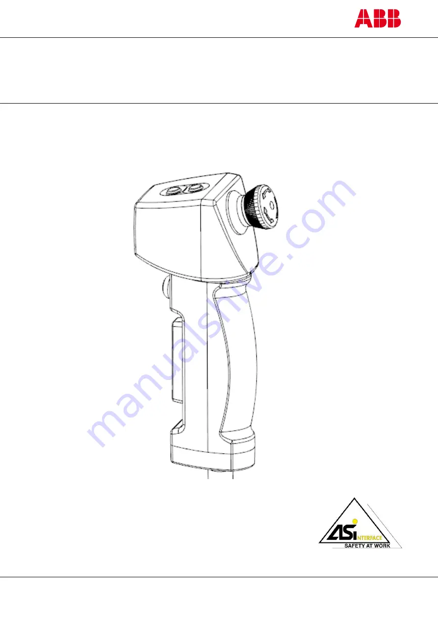
HD5-B-901
(CustomerSolution)
Three position enabling device with safe AS-i slave
Page 1: ...ABB AB JOKAB SAFETY Varlabersvägen 11 SE 43439 Kungsbacka www abb com lowvoltage Original instructions HD5 B 901 CustomerSolution Three position enabling device with safe AS i slave ...
Page 2: ...lications Several examples of applications that require special attention are listed below These examples are not intended to be an exhaustive list of all the possible applications of the products and they should not be understood as meaning that products are suitable for the potential uses specified Use outside use where there is the possibility of chemical exposure or electrical interference or ...
Page 3: ...NAL BUTTON NO 1 10 ADDITIONAL BUTTONS NO 3 AND NO 4 10 SIGNAL LED 11 HOME POSITION DETECTOR 11 ASSIST LIGHT FLASHLIGHT 11 VIBRATION 12 STATUS LED FOR AS I BUS 12 CONNECTION WITH AS I NETWORK 13 Fixed connection 13 4 INSTALLATION 14 GENERAL 14 INSTALLING THE HOLDER 14 5 COMMISSIONING 15 FUNCTIONAL TEST 15 6 REVIEW MAINTENANCE AND CLEANING 16 PRODUCT DATA 16 7 DISPOSAL 16 8 OPERATION 17 THREE POSITI...
Page 4: ...19 INFORMATION ON POSITIONS 20 10 ACCESSORIES 21 ACTIVE HOLDER HD5 M 001 21 PASSIVE HOLDER HD5 M 002 21 11 TECHNICAL DATA 22 AS I DATA 25 CUSTOM VERSIONS HD5 B 901 25 12 DIMENSIONS 26 3 POSITION ENABLING DEVICE 26 DEVICE SPECIFIED HOLDER 26 13 EC DECLARATION OF CONFORMITY 27 ...
Page 5: ...them and the hazards they pose Prerequisites It is assumed that the reader of this document has the following knowledge Basic knowledge of ABB JOKAB SAFETY products Knowledge of the AS i Bus system Knowledge of safety products Knowledge of safety control devices with functions relevant to safety Knowledge of related facilities Special instructions Please pay attention to the following special inst...
Page 6: ...feedback are transmitted from additional integrated command buttons and sensors to the AS i logic and from the AS i logic to the enabling device via a third unsafe slave The enabling device is connected to the AS i Bus in the usual way using a fixed spiral cable or via a M12 connector built into the device If you have any questions regarding the existing configurations or the possibilities for a c...
Page 7: ...ith the instructions or a use that is not in accordance with the specified instructions as well as the improper installation or operation of the device may adversely affect the safety of the user and the facility A safety logic unit configured in accordance with the specified use of the product is required to monitor evaluate the signals of the enabling device allowing the product to be used the s...
Page 8: ...switch identifies the three positions OFF ON OFF using O and I the movement direction from left to right as well as the possible ways to move the switch An important feature of the three position enabling switch is that when shifting back from position 3 the ON position is not actuated i e the contacts remain open The three positions function as follows Position 1 O OFF mode enabling button has no...
Page 9: ...ons in all operating modes of the machine without affecting any facilities which are designed to release trapped persons No start command whether intentional unintentional or unexpected should be able to affect working processes that were stopped by initiating the emergency stop function until the emergency stop function has been reset manually If it is possible to remove emergency stop buttons e ...
Page 10: ...ex finger Note on actuation The button must be actuated by pressing it down vertically to an angle of between 0 and 15 If the angle is exceeded when actuating the switch there is a possibility that the switch contact may be damaged and the switching cycles specified in the technical data will not be achieved Additional buttons No 3 and No 4 These buttons are installed on the grey housing They can ...
Page 11: ...s for short periods in which the ambient light is not sufficient The controls are user defined and can be controlled in a user defined way via the AS i Bus When using these you must comply with the following Notice on duty cycle On time 60 max 15 min ambient temperature 35 C On time 40 max 10 min ambient temperature 35 C Calculation o On time percentage on time on time off time x 100 o On time D 1...
Page 12: ...f necessary instructed in order to detected potential hazards arising from the function Due to ignorance and possibly the following shock there is a risk of accident Status LED for AS i Bus One green and one red LED will inform you about the status of the slave on the AS i Bus The LEDs are positioned in a way that means they are not directly visible when the enabling device is placed in the holder...
Page 13: ...ration of the enabling device with an integrated emergency stop button is being used Note on the connection cable If the enabling device is connected using a spiral cable and more than three HD5 B xxx are used on an AS i cable you must reduce the AS i cable by 12m per device Attention Please note if an emergency stop button is implemented in the enabling device and the connection becomes deconnect...
Page 14: ...ed to follow the procedure shown in the picture on the right using an M12 connector Normally the M12 connector should be attached to Pin1 AS i and Pin 3 AS i Please ensure in accordance to the national electrical codes the separate laying of cable that serve the power supply control and main circuits and the cable that serve to transmit control signals The connection cable of this device must be l...
Page 15: ...the device is not tampered with and ensure the intended use see scope of application is complied with Attention Other protective measures must be taken in order to protect other people in the same or adjacent hazardous area Functional Test At first commissioning after installation a functional test based on the application case must be carried out in accordance with current guidelines for the case...
Page 16: ...dged tools can weaken or penetrate the surface which results in the protection class being lost in a relatively short space of time Dirt and moisture may penetrate the housing The use of cleaning agents containing solvents should be avoided This is not only to protect the surfaces but also to protect the health of employees Attention If the device doesn t have functionality or the device has becom...
Page 17: ...sent to the controls start process o The process stops when the button is put into its end position position 3 stop status Position 3 Stop status o Button has been moved into the third and final position o Signal sent to the controls stop process o The button must be put into idle mode position 1 before it can be put back into operating mode position 2 Emergency stop button The emergency stop butt...
Page 18: ...th the HD5 M 001 holder provides information as to whether the enabling device is in its holder Assist light flashlight This can be turned on in a way that is defined by the user so that the work areas can light up for a short selected length of time Caution Please pay attention to the instructions in section 3 Functional description Vibration One application of this function is when using the ena...
Page 19: ...1 2TLA920502R0002 Position number Function Additional information 1 Enabling button 2 Emergency stop button Feedback LED integrated into emergency stop button 3 Additional button 1 4 5 Additional button 3 6 Additional button 4 7 Red signal LED 8 Green signal LED 9 Home position detector only possible with the HD5 M 001 holder 10 11 Assist light flashlight 12 Vibration 13 Permanent connection 2x0 7...
Page 20: ...p button Feedback LED integrated Information on positions No 7 red signal LED No 3 additional button 1 No 5 additional button 3 No 11 Assist light flashlight No 6 additional button 4 No 13 connection No 8 green signal LED integrated into housing No 9 home position sensor No 10 No 12 vibration motor ...
Page 21: ...eated in accordance with hygienic design principles Type name HD5 M 001 Item number 2TLA920509R0001 Passive holder HD5 M 002 This holder functions in the same way and has the same properties when it comes to holding the enabling device as the holder HD5 M 001 however the home position detector is not activated when the enabling device is hung up Information on this is detailed in the list below ho...
Page 22: ...PPH G30 Operating buttons TPE Actuating force enabling button approx 20 N 1 2 approx 45 N 2 3 Actuating force additional buttons approx 3 N additional buttons 1 and 2 approx 7 N additional buttons 3 and 4 Mechanical electrical durability of enabling button 1 x 10⁶ switching cycles position 1 position 2 1 x 10⁵ switching cycles position 2 position 3 Mechanical reliability B10D enabling button B10D ...
Page 23: ...26 need to be terminated in a terminal block or similar connection device or shall be prepared by a wire termination Response time on the AS i bus HD5 B xxx The enabling device meets the requirements of AS Interface Safety at Work in all respects An additional extension of the response time in the transition to the safe state is not carried out by this ABB AS i Monitor Pluto Response time on the A...
Page 24: ...EC Machines 2014 30 EU EMC 2011 65 EU RoHS2 2015 863 RoHS3 EN ISO 12100 1 2010 EN ISO 13849 1 2015 EN 62061 2015 EN 60204 1 2006 A1 2009 SILCL 3 PL e category 4 UL CSA 60947 5 1 UL CSA 60947 5 5 only for variants with an E Stop is included Certificates TÜV Süd UL AS International Assoziation CE ...
Page 25: ... feedback LED in emergency stop button OFF 1 feedback LED in emergency stop button ON S 0 B 2 E Address 02 upon delivery Safe code1 D 0 enabling button Safe code1 D 1 Safe code2 D 2 Safe code2 D 3 S 7 0 3 E Address 03 upon delivery Input Non safe DI 0 0 additional button 1 tab not actuated 1 additional button 1 tab actuated DI 1 0 home position sensor enabling device not hung up in holder 1 home p...
Page 26: ...2CDC172114M0201 26 www abb com lowvoltage 2019 09 06 V1 3 12 Dimensions o All the dimensions are given in millimeters mm 3 position enabling device Device specified Holder ...
Page 27: ...2CDC172114M0201 27 www abb com lowvoltage 2019 09 06 V1 3 13 EC DECLARATION OF CONFORMITY ...