background image

Product manual  


20.02.2024


ABB-free@home

®


BI-F-2.0.x2 

2-gang binary input, flush-mounted


BI-F-4.0.x2

4-gang binary input, flush-mounted

Branding -- Release 2018-01-01 

Summary of Contents for free@home BI-F-2.0.x2

Page 1: ...Product manual 20 02 2024 ABB free home BI F 2 0 x2 2 gang binary input flush mounted BI F 4 0 x2 4 gang binary input flush mounted Branding Release 2018 01 01...

Page 2: ...2 Overview of types 8 3 3 Functions 9 3 4 Device overview 13 4 Technical data 14 4 1 Dimensional drawings 15 5 Connection installation mounting 16 5 1 Planning instructions 16 5 2 Safety instructions...

Page 3: ...d damage to property and ensure both reliable operation and a long service life for the device Please keep this manual in a safe place If you pass the device on also include this manual along with it...

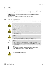
Page 4: ...symbol in connection with the signal word Danger indicates an imminently threatening danger which leads to death or serious irreversible injuries Warning Serious damage to health The respective warnin...

Page 5: ...ively by the user operator The device is not intended for the following Unauthorized structural changes Repairs The use in bathroom areas Insert with an additional bus coupler 2 4 Target group Qualifi...

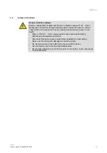
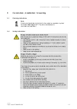
Page 6: ...can result in electric shock burns or even death Work on the 100 240 V supply system may only be performed by authorised and qualified electricians Disconnect the mains power supply before installatio...

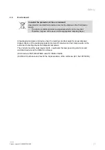
Page 7: ...ng depot All packaging materials and devices bear the markings and test seals for proper disposal Always dispose of the packaging material and electric devices and their components via the authorized...

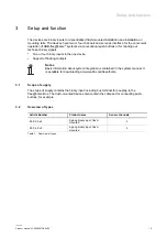
Page 8: ...ts in the one device Support of floating contacts Notice Basic information about system integration is contained in the system manual It is available for downloading at www abb com freeathome 3 1 Scop...

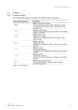
Page 9: ...ol of ABB free home functions Name Window contact Signals an open window Application Automatic deactivation of the heating when the window is open Name Frost alarm Triggers a frost alarm Application e...

Page 10: ...an alternating long press of the push button rocker A brief press switches the lamp on or off With a double push button the long press of the rocker s connected to channel coupling channels A B for B...

Page 11: ...he rocker connected to this channel After the activation the operation of the affected switch actuator channel is blocked by all other devices In the parameter settings of the binary input the forced...

Page 12: ...annel of the blind actuator is blocked to make movement impossible During rain or wind alarm the blind is moved to the top end position and then the associated channel of the blind actuator is blocked...

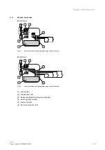
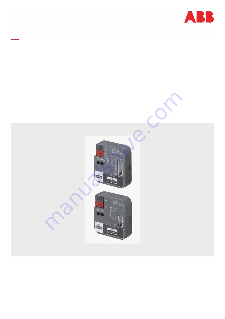
Page 13: ...2 Fig 1 Overview of devices 2 gang binary input flush mounted BI F 4 0 x2 Fig 2 Overview of devices 4 gang binary input flush mounted 1 Label holder 2 Identification LED 3 Device identification during...

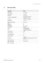
Page 14: ...mm Wire stripping 5 6 mm Admissible cable length 10 m max Input BI F 2 0 x2 BI F 2 0 x2 Polling voltage Input current 2 4 20 V pulsed 0 5 mA Safety Short circuit proof Overload protection Reverse pola...

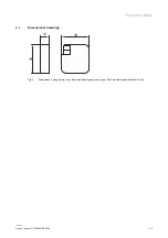
Page 15: ...Technical data Product manual 2CKA000073B5466 15 4 1 Dimensional drawings 12 39 40 Fig 3 Dimensions 2 gang binary input flush mounted 4 gang binary input flush mounted specifications in mm...

Page 16: ...rrect polarity Observe the relevant standards Danger Electric voltage Install the device only if you have the necessary electrical engineering knowledge and experience Incorrect installation endangers...

Page 17: ...73B5466 17 5 3 Circuit diagrams BI F 2 0 x2 Fig 4 Electrical connection 2 gang binary input flush mounted BI F 4 0 x2 Fig 5 Electrical connection 4 gang binary input flush mounted NC 1 2 3 4 5 6 Black...

Page 18: ...blished by means of the enclosed bus connection terminal The inputs outputs are connected according to the circuit diagram via six plug in connecting cables that are approx 30 cm long The connecting c...

Page 19: ...ist see system manual System Access Point Wires not required are to be insulated The bus connection is established by means of the enclosed bus connection terminal The device is ready for operation af...

Page 20: ...ally connected to the free home Bus bus log themselves automatically into the System Access Point They transmit information about their type and supported functions Functions on page 9 During initial...

Page 21: ...y only be visible on the left see arrow 1 Tap on button Devices scenes groups or switch icon The Building plan view opens Fig 6 Opening the building plan and list of components example illustration 2...

Page 22: ...t of the menu bar example illustration Notice for operation via a mobile phone The building plan floor plan is not available in the app for mobile phones Use the list view of the device configuration...

Page 23: ...pplication selected Identification via serial number Fig 9 Identification via serial number 5 Compare the serial number and the short ID of the identification label printed on the device with the numb...

Page 24: ...fy them by switching the actual device Fig 10 Identification via switching example illustration 1 Open the device list 2 Press the Identification button 1 and then switch the actual device Or as alter...

Page 25: ...a name Fig 11 Assigning a name example illustration 3 Enter a name that is easy to understand and under which the application is to be displayed later e g South wall weather station 4 Tap the Save but...

Page 26: ...can be made for each channel The settings are made via the web based user interface of the System Access Point or the ABB free home App Next Select device Fig 12 Selecting device 1 Select the device i...

Page 27: ...you do not enter via the main menu click on the icon 2 Fig 13 Open overview of devices example illustration 2 Select the Functions button 3 The overview of devices opens Here you can view all devices...

Page 28: ...B5466 28 Fig 14 Overview of devices example illustration 3 Tap on a device category The list of available devices opens 4 Tap on the device whose information you want to edit A new window with informa...

Page 29: ...mmissioning Product manual 2CKA000073B5466 29 6 3 Parameters Information about the device name the position in the building and additional settings are illustrated in the device menu Fig 15 Device men...

Page 30: ...etectors Window contact Heating Cooling Frost alarm Rain alarm Wind alarm 6 Parameters Contact type In this drop down menu the contact type can be selected The following values are available Normally...

Page 31: ...he list of functions via the Floor plan button 6 4 1 Linking sensor and actuator Configuring positioning and linking of the devices is carried out via menu Devices scenes and groups Fig 16 Linking sen...

Page 32: ...nt There the corresponding function Light scene or Light group is to be added and linked with the corresponding channel of a binary sensor to which a push button is connected for calling up light scen...

Page 33: ...device must be guaranteed for operation testing inspection maintenance and repairs according to DIN VDE 0100 520 9 1 Cleaning Caution Risk of damaging the device When spraying on cleaning agents thes...

Page 34: ...Notes Product manual 2CKA000073B5466 34 10 Notes...

Page 35: ...nctions 11 23 I Identification 26 Identification label 26 Improper use 5 Information and symbols used 4 Initial commissioning 23 Intended use 5 L Links 34 actuator 35 sensor 35 M Maintenance 37 Mounti...

Page 36: ...contents of this document without prior notice The detailed specifications agreed upon apply for orders ABB accepts no responsibility for possible errors or incompleteness in this document We reserve...

Reviews: