


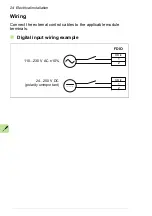


22 Electrical installation
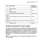
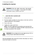
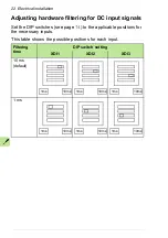
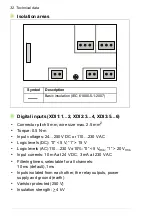
Adjusting hardware filtering for DC input signals
Set the DIP switches (see page
) to the applicable positions for
the necessary inputs.
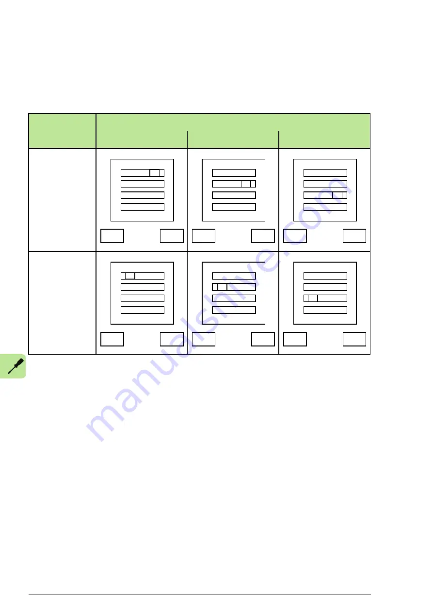
This table shows the possible positions for each input.
Filtering
time
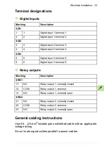
DIP switch setting
XDI1
XDI2
XDI3
10 ms
(default)
1 ms
1ms
10ms
1ms
10ms
1ms
10ms
1ms
10ms
1ms
10ms
1ms
10ms
Summary of Contents for FDIO-01
Page 4: ......
Page 10: ...10 Safety instructions ...
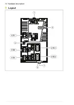
Page 14: ...14 Hardware description Layout 3 5 1 1 XRO1 XRO2 XDI1 XDI2 XDI3 4 2 ...
Page 16: ...16 Hardware description ...
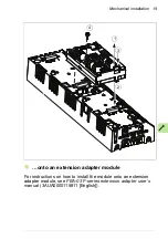
Page 20: ...20 Mechanical installation ...
Page 26: ...26 Start up ...
Page 28: ...28 Diagnostics ...
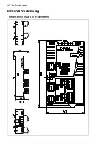
Page 30: ...30 Technical data Dimension drawing The dimensions are in millimeters ...
Page 34: ...34 Technical data ...