


Manual Energy Storage Inverter ESI-S
Hardware description 23
ESI-Manager setup for digital input: Activ.
Aux.
(a)
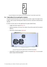
Local ON/OFF buttons
ESI-Manager setup for digital input: Edge
ON
(a) (b)
No
effect
Inverter
starts
on
rising
edge
Local ON/OFF buttons
ESI-Manager setup for digital input: Edge
OFF
(a) (b)
No
effect
Inverter
stops
on
rising
edge
Local ON/OFF buttons
ESI-Manager setup for digital input: Edg
ON/OFF
(a) (c)
No
effect
Inverter
starts
on
first
rising edge, stops on
second rising edge etc.
Remarks:
(a)
: In order for this function to be activated, the ESI-Manager has to be set up accordingly. To
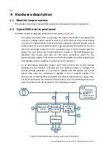
do this, navigate to [/Welcome/Settings/Customer set./Digital Inputs]
(b)
: When using the Edge ON function the inverter can only be switched on by applying voltage
to the digital input considered. It is therefore recommended in that case to configure and
cable the second digital input as Edge OFF.
(c)
: When using this function, the inverter stop and start can be controlled by one digital input
leaving the other one available for an additional remote control or switching between main
and auxiliary settings.
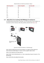
Information on cabling the digital input contacts is given in
Information on setting up the digital inputs with the ESI-Manager is given in
Section
By default, the digital inputs are disabled.
In a master-master inverter arrangement, only the master that has the control over the
complete system will monitor its digital outputs. For full redundant functionality, it is
recommended to cable the digital inputs of all the units in the inverter system.
2
Digital Outputs 1 to 6
With each digital output different inverter conditions can be associated. The association
between the inverter condition and the digital outputs is done with the ESI-Manager.
gives an overview of the possible ESI-Manager settings for a digital output and
the effect on the corresponding digital output relay.
Table 9: inverter conditions that can be related to the digital outputs
ESI-Manager setting for digital
output
(a)
Output relay closes when…
Auxil. ON
The auxiliary power is present in the main inverter
enclosure and the main controller is communicating
with the ESI-Manager
ESI running
The inverter is ‘on’ (IGBTs switching) or in ‘standby’
(main contactor closed but IGBTs not switching)
Full load
The inverter is running under full load condition