Endura AZ40 | Sensor assembly | Orifice and seals kit |
INS/ANAINST/007-EN Rev. B
15
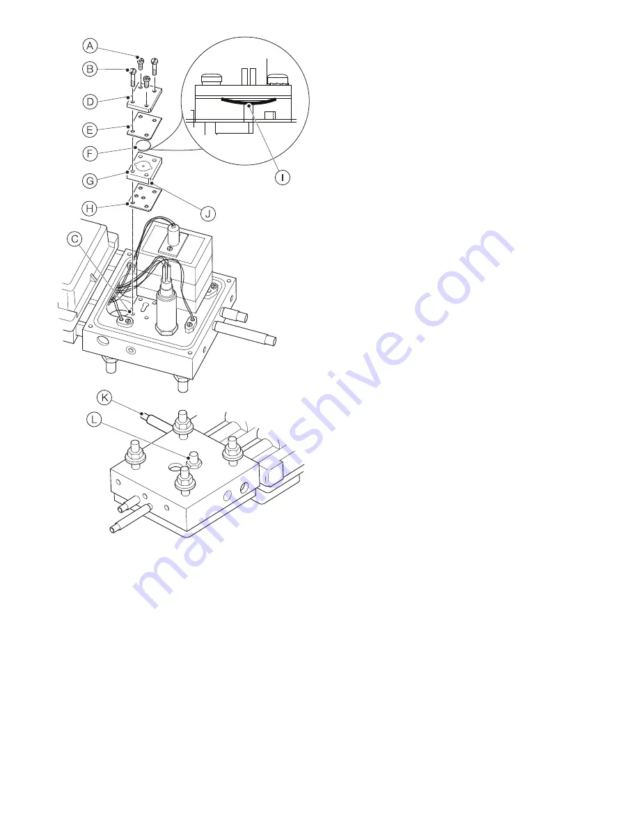
Fig. 8.7 Replacing sensor assembly flow disk
Page 1: ...nd 8 4 pages 4 4 6 and 12 Replacing sensor assembly flow disk Sections 4 5 6 and 8 5 pages 4 4 6 and 14 Kit contains Orifices gaskets seals This publication Tools required Transmitter door key supplie...
Page 2: ...contain fibrous material that can be a health hazard if airborne The material predominantly aluminosilicate refractory fibres CAS 142844 00 6 Refractory ceramic fibres RCF are classified as Category 1...
Page 3: ...sensor probe assembly must be mounted in accordance with the information supplied in Operating instruction OI AZ40 EN Suitable lifting equipment must be available when installing removing the sensor...
Page 4: ...the sensor air and test gas supplies at the process Referring to Fig 5 2 1 Disconnect air line B and test gas line C at sensor D DANGER Serious damage to health risk to life The transmitter must be i...
Page 5: ...embly B to mounting flange C Set items aside for re use 2 Carefully remove the sensor assembly and the attached probe including filter assembly from the process 3 Temporarily cover process opening unt...
Page 6: ...s kit component locations Fig 6 1 Orifice and seals kit component locations on sensor assembly Key A CO orifice see Section 7 page 7 B O2 orifice see Section 7 page 7 C CO heater block gaskets see Sec...
Page 7: ...a 1 4 in allen key wrench to secure CO orifice pipe plug A in place in the CO orifice chamber 9 Use a 5 32 in allen key wrench to secure O2 orifice D 1 notch in head in place in the O2 orifice chambe...
Page 8: ...flat bladed screwdriver to unscrew 4 captive cover retaining screws A and remove cover B Retain cover for re use 2 Use a medium flat bladed screwdriver to unscrew 2 captive cover retaining screws C an...
Page 9: ...crewdriver to depress the spring connector in each terminal and withdraw the wires from the terminal housing 3 Unscrew O2 sensor A from manifold block B using a 7 8 in spanner wrench and withdraw the...
Page 10: ...th attached washer K 14 Re fit COe block insulation A in the reverse order of removal 15 Apply a light coating of an anti seize compound suitable for temperatures up to 200 C 392 F to sensor clamp pla...
Page 11: ...Endura AZ40 Sensor assembly Orifice and seals kit INS ANAINST 007 EN Rev B 11 Fig 8 4 Replacing sensor assembly gaskets...
Page 12: ...ted correctly 7 Fit the nozzle B into the aspirator A ensuring it is seated correctly 8 Apply a light coating of an anti seize compound suitable for temperatures up to 200 C 392 F to the threaded port...
Page 13: ...Referring to Fig 8 6 If a recommended 2 stage filtration system A is fitted in the instrument air line replace the filters in accordance with manufacturers instructions Fig 8 5 Replacing Cleaning sen...
Page 14: ...rner of the flow disk assembly J with the upper right hand corner Ensure screw holes are aligned correctly 11 Apply a light coating of anti seize compound suitable for temperatures up to 200 C 392 F t...
Page 15: ...Endura AZ40 Sensor assembly Orifice and seals kit INS ANAINST 007 EN Rev B 15 Fig 8 7 Replacing sensor assembly flow disk...
Page 16: ...ts in this document and in the subject matter and illustrations contained therein Any reproduction disclosure to third parties or utilization of its contents in whole or in parts is forbidden without...