


Modifications reserved
Page 48/79
6.4
Communication interfaces
The UPS cabinet is provided with a communication card that provides the system information
Communication card (next to the distribution):
•
Input Interfaces
X1 (Phoenix terminals)
•
Output Interfaces :
X2 DRY PORTs ,volt-free contacts (Phoenix
terminals)
•
Smart Port JD1 / RS232 Sub D9 / female: Interface (UPS system to computer)
•
USB
Interface (UPS system to computer)
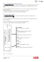
Two LEDs are located on the interface board (3):
•
Green LED
showing the status of the Interface:
- Fast blinking: 2 times/sec = interface is OK
•
Red LED
Board alarm (indicates a possible replacement of
the board)
6.4.1
Customer interface and DRY PORTs
All the input and output interfaces are connected to phoenix terminals (cable 0.5 mm2).
6.4.1.1
Output interfaces: terminal blocks x2 (DRY PORTs)
•
Provision of signals for the automatic and orderly shutdown of servers, AS400 or building
automation systems
6.4.1.2
Input interfaces: teminal blocks X1
•
Connection of remote shut down facilities, generator operation, customer’s specials
Refer to the chapter 7.2.
Summary of Contents for DPA UPScale ST120
Page 1: ... Copyright 2017 ABB All rights reserved User Manual DPA UPScaleTM ST S2 10 200 kW ...
Page 76: ...Modifications reserved Page 76 79 10 Attachments 10 1 Technical data sheet ...
Page 78: ......
Page 79: ... Copyright 2017 ABB All rights reserved Technical data sheet DPA UPScaleTM ST S2 10 200 kW ...
Page 104: ......
Page 105: ... Copyright 2017 ABB All rights reserved Technical data sheet DPA UPScaleTM ST S2 10 200 kW ...


