


Installation
D184B111U02 CoriolisMaster
FCM2000
23
Pos: 22 /Überschriften/1/G - I/Installation @ 0\mod_1129814872309_3101.doc @ 3152 @ 11
4 Installation
Pos: 23 /==== Wechsel ein- auf zweispaltig ==== @ 0\mod_1130421847171_3101.doc @ 3828 @
Change from one to two columns
Pos: 24.1 /Überschriften/1.1/2-spaltig/D - F/Einbaubedingungen @ 2\mod_1155119709593_3101.doc @ 38554 @ 22
4.1 Installation
Requirements
Pos: 24.2 /Überschriften/1.1.1/1-spaltig/Allgemeine Hinweise @ 6\mod_1168441965125_3101.doc @ 57860 @ 33
4.1.1 General
information
Pos: 24.3 /==== Wechsel ein- auf zweispaltig ==== @ 0\mod_1130421847171_3101.doc @ 3828 @
Change from one to two columns
Pos: 24.4 /Technische Daten / Datenblatt/Durchfluss/FCM2000/Einbaubedingungen/Allgemeine Hinweise @ 5\mod_1166449207375_3101.doc @ 52671 @ 55555555
Inspection
Before installing the flowmeter sensor, check for physical damage
due to possible improper handling during shipment. All claims for
damage are to be made promptly to the shipper.
Installation Requirements / System Sizing Information
The FCM2000 is suitable for both indoor and outdoor installations.
The standard instrument meets the requirements of Protection Class
IP 67. The primary is bidirectional and can be installed in any
orientation. It is important to ensure that the meter pipes are always
completely filled with fluid.
The corrosion resistance of the fluid wetted materials must be
evaluated.
The following points are to be considered during installation:
The preferred flow direction is indicated by the arrow on the
flowmeter sensor. Flow in this direction will be indicated as positive (a
forward/reverse flow calibration is available as on option).
Installation position
The FCM2000 operates in any orientation. The optimal installation
orientation is vertical with the flow upwards.
Supports
In order to support the weight of the flowmeter sensor and to ensure
reliable measurements when adverse external effects exist (e.g.,
vibrations), the primary should be installed in rigid pipelines. Two
supports or hangers should be installed symmetrically and stress free
in close proximity to the in- and outlet process connections.
Shut Off Devices
To conduct a system zero adjustment, shut off devices are required
in the pipeline:
-
in horizontal installation at the outlet,
-
in vertical installation at the inlet.
When possible, shut off devices should be installed both up- and
downstream from the flowmeter sensor.
Inlet Straight Sections
The mass meter does not require any flow conditioning inlet straight
sections. Care should be exercised to ensure that any valves, gates,
sight glasses, etc., do not cavitate and are not set into vibration by
the flowmeter sensor.
System Design Information
•
The presence of gas bubbles in the fluid can result in erroneous
measurements, particularly in the density measurement.
Therefore the flowmeter sensor should not be installed at the
highest point in the system. Advantageous are installations in low
pipeline sections, e.g., at the bottom of a U-section in the pipeline
(invert).
•
Long drop lines downstream from the flowmeter sensor should be
avoided to prevent the meter tube from draining.
•
Installation should be performed as stress free as possible.
•
The flowmeter sensor should not come in contact with any other
objects. Attachments to the housing are not permissible.
•
When the cross-section of the connecting pipeline is larger than
the flowmeter sensor size, suitable standard reducers should be
installed.
•
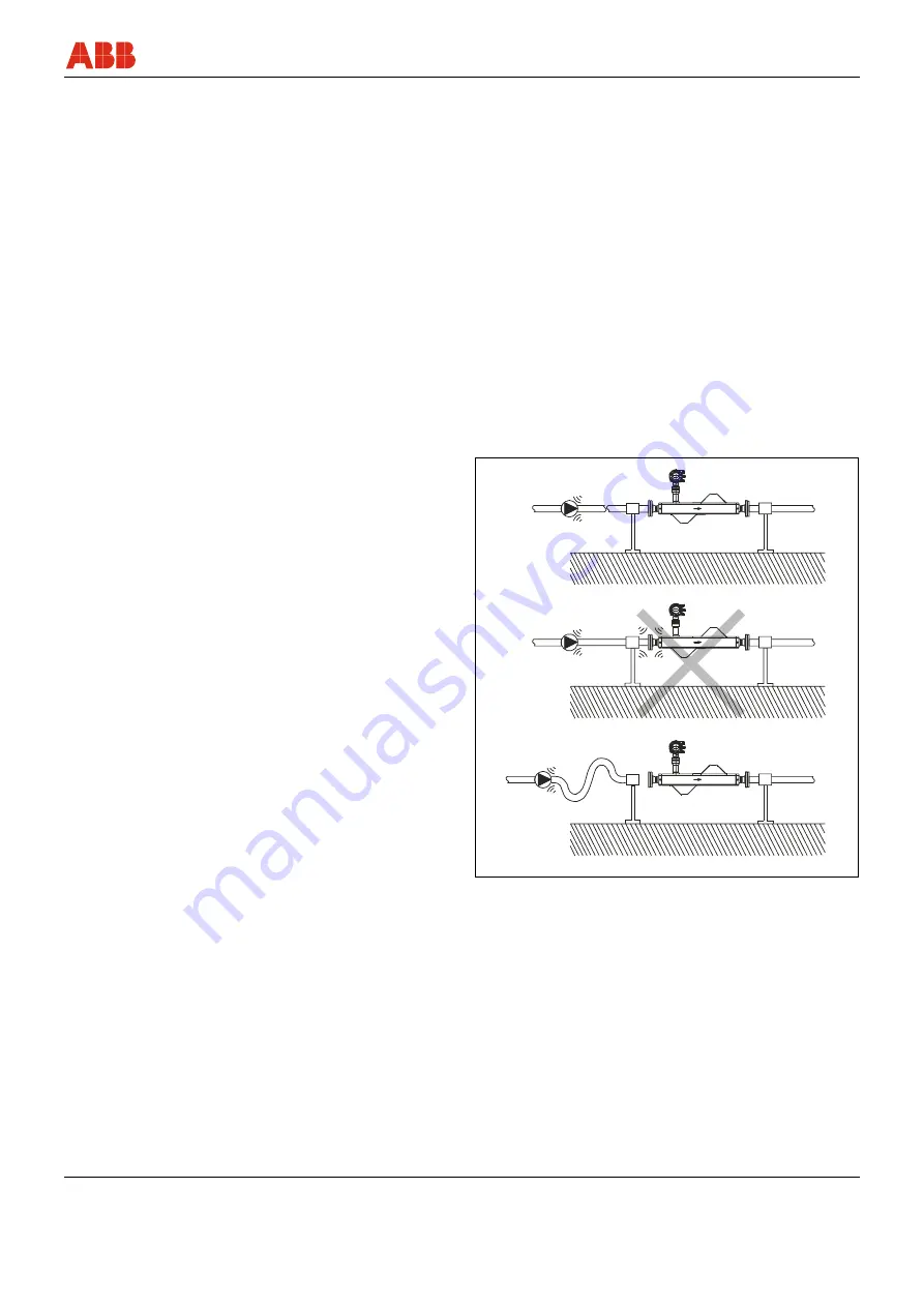
If strong vibrations exist in the pipeline, they should be damped
using elastic pipeline elements. The damping devices must be
installed beyond the supported flowmeter section and outside of
the section between the shut off devices. The direct connection of
flexible elements to the flowmeter sensor should be avoided.
G00361
Fig. 12:
Vibrations
Summary of Contents for CoriolisMaster FCM2000
Page 112: ...Appendix 112 CoriolisMaster FCM2000 D184B111U02...
Page 113: ...Appendix D184B111U02 CoriolisMaster FCM2000 113...
Page 114: ...Appendix 114 CoriolisMaster FCM2000 D184B111U02...
Page 115: ...Appendix D184B111U02 CoriolisMaster FCM2000 115...
Page 116: ...Appendix 116 CoriolisMaster FCM2000 D184B111U02...
Page 117: ...Appendix D184B111U02 CoriolisMaster FCM2000 117...
Page 118: ...Appendix 118 CoriolisMaster FCM2000 D184B111U02...
Page 119: ...Appendix D184B111U02 CoriolisMaster FCM2000 119...
Page 120: ...Appendix 120 CoriolisMaster FCM2000 D184B111U02...


