background image

Declaration_Part_FBD.png

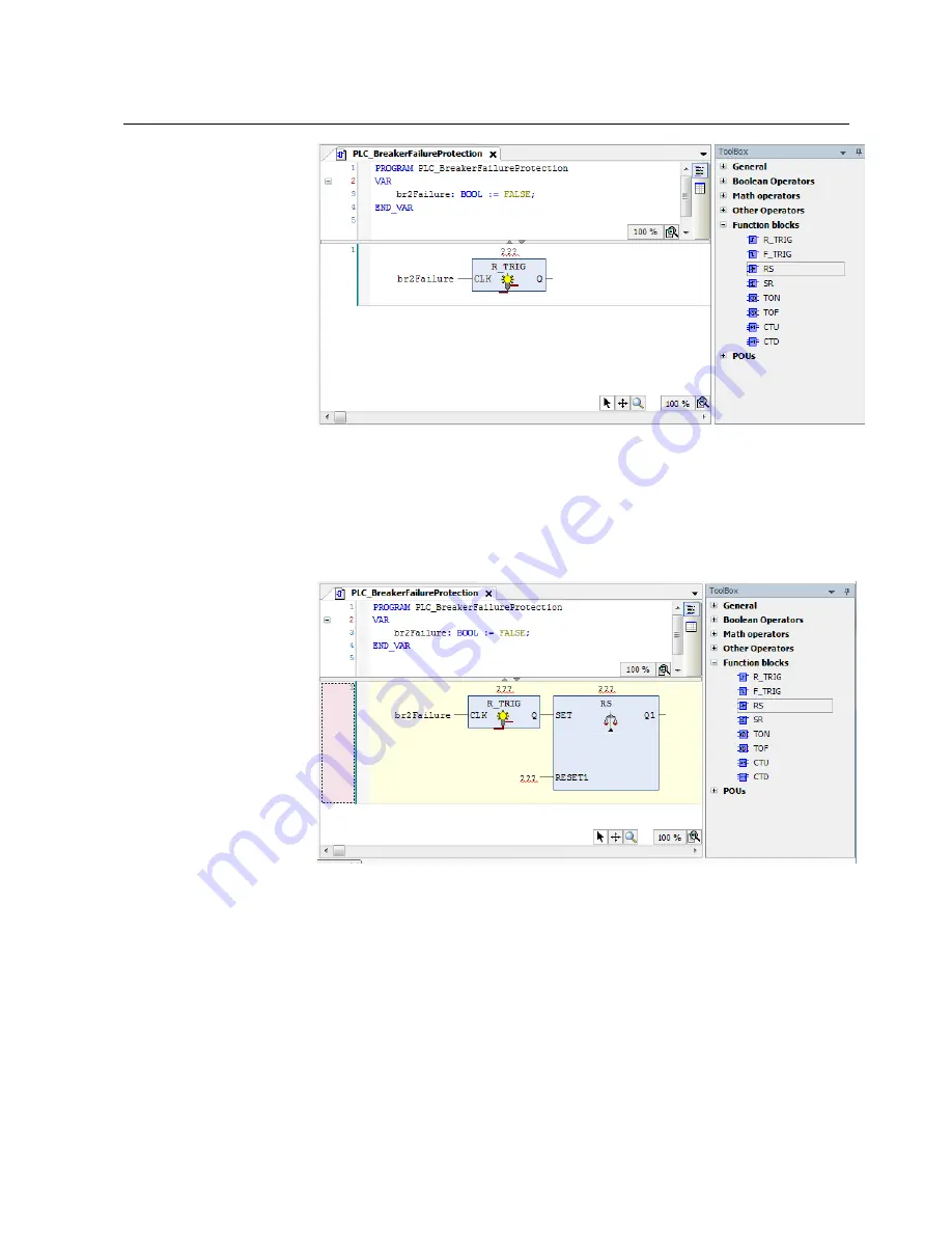
Figure 4.4-4 Declaration part of the Function Block Diagram

In the declaration part of the diagram, the br2Failure variable is defined as a Boolean
variable and initialized to FALSE.

15. Add a second function block in the ToolBox by selecting the RS (Reset Set function

block) from the Boolean Operators catalog and dragging and dropping it to the
output point of the R TRIG object.

Adding_AND_gate.bmp

Figure 4.4-5 Adding Reset Set function block

The logic can be built as follows.

33

COM600 series 5.1

1MRS756738

Logic Processor User's Manual

Summary of Contents for COM600 series 5.1

Page 1: ... COM600 series 5 1 Logic Processor User s Manual ...

Page 2: ......

Page 3: ...DeSys programming environment 16 3 3 2 Adding symbol configuration 17 3 3 3 Add POU to Application MainTask 19 3 3 4 Setting device path 20 3 3 5 Downloading and starting PLC application 22 3 3 6 Logic Editor Online Help 23 3 4 Making cross references 24 3 5 Creating virtual data objects in the Logic Processor IED 25 3 6 Downloading Logic Processor OPC Server configuration 27 4 Application example...

Page 4: ...4 9 Making cross references 37 Index 39 4 1MRS756738 COM600 series 5 1 Logic Processor User s Manual ...

Page 5: ...lves that each intended application is suitable and acceptable including that any applicable safety or other operational requirements are complied with In particular any risks in applications where a system failure and or product failure would create a risk for harm to property or persons including but not limited to personal injuries or death shall be the sole responsibility of the person or enti...

Page 6: ...the product standards EN 50263 and EN 60255 26 for the EMC directive and with the product standards EN 60255 1 and EN 60255 27 for the low voltage directive The product is designed in accordance with the international standards of the IEC 60255 series Trademarks 1 4 ABB is a registered trademark of ABB Group All other brand or product names men tioned in this document may be trademarks or register...

Page 7: ...e out of range the following message is displayed Entered value is not valid The value must be 0 30 You can be asked to enter the string MIF349 in a field The string is shown as follows in the procedure MIF349 Variables are shown using lowercase letters sequence name Use of symbols 1 7 This publication includes warning caution and information icons that point out safety related conditions or other...

Page 8: ...ructures Data Object DO The data set is the content basis for reporting and logging The data set contains references to the data and data attribute val ues Data Set A physical device that behaves as its own communication node in the network for example protection relay Device Change of process data or an OPC internal value Normally an event consists of value quality and timestamp Event A physical ...

Page 9: ...cess DA Data Object DO Gateway component connecting two communication networks together GW Web Human Machine Interface WebHMI International Electrotechnical Commission IEC Intelligent Electronic Device IED Local Area Network LAN Logical Device LD Logical Node LN Network Control Center NCC Object Linking and Embedding OLE OLE for Process Control OPC Protection Control P C Programmable Logic Control...

Page 10: ...1MRS756567 DNP 3 0 Serial Master OPC User s Manual 1MRS755495 DNP 3 0 Serial Slave OPC User s Manual 1MRS755382 IEC 60870 5 101 Slave OPC User s Manual 1MRS756703 IEC 60870 5 101 Master OPC User s Manual 1MRS752278 IEC 60870 5 103 Master OPC User s Manual 1MRS756738 COM600 Logic Processor User s Manual 1MRS756126 Modbus Serial Master OPC User s Manual 1MRS756913 Modbus Serial Slave OPC User s Manu...

Page 11: ... To facilitate substation and grid automation solutions in IEC and ANSI market areas a variant based system similar to Relion 615 and 620 series is being followed from COM600 5 0 release The main reasons for such an approach are the following To ensure all COM600 product series features are advantageously used in end cus tomer projects in the medium voltage substation automation domain To ensure a...

Page 12: ...is handled by the Logic Processor OPC Server It enables the logic variables to be connected to the process signals available via different communication protocols in COM600 The shortest possible data transfer cycle between process signals and logic variables is 50 ms The logic program might not detect progress data changes that are faster than or close to the transfer cycle time The default task i...

Page 13: ...3S Smart Software Solutions GmbH www 3s software com Features 2 4 Logic editor CoDeSysV3 programming system supports all five standard programming languages defined by the IEC 61131 3 standard Ladder diagram LD Sequential Function Charts SFC Function Block Diagram FBD 13 COM600 series 5 1 1MRS756738 Logic Processor User s Manual ...

Page 14: ...asurement values Controlling process control signals from logic variables Logic variable presented as 61850 data object for other COM600 component WebHMI slave clients Controls from WebHMI or NCC via slave client to logic variable The following techniques are used OPC Data Access Server v 1 0 2 0 OPC Alarms and Events Server v 1 10 OPC Data Access Client v 2 0 IEC 61850 data modeling For example m...

Page 15: ...lowing tasks 1 Building Communication Structure objects for the Logic Processor 2 Creating the logic in the CoDeSys programming environment 3 Building a cross reference between process data and logic variables data by using the Cross References tool 4 Creating virtual data objects in the Logic Processor OPC server and connecting the data objects to logic variables with the object properties Buildi...

Page 16: ...Logic Editor The CoDeSys programming environment will start as a new application instance 2 Select CoDeSys from the taskbar If this is the first time to launch CoDeSys an empty project with the same name as the SAB600 project will be opened If a project has already been saved the saved project will be opened In the new default project device CoDeSys Control Win V3 has already been added and it sho...

Page 17: ...ciated with them These variables will be available for external communication through OPC standard DA access The variables that are selected in symbol configuration are made available in SAB600 Logic Processor Cross References tool to set up data connection with other OPC Protocol DNP Modbus IEC 61850 servers clients in the SAB600 communication structure All variables must be defined for the PLC A...

Page 18: ...l POUs in the open project 5 Click Build to view available symbols All latest variables available from all POUs after compilation are displayed 6 Select each of the variables that are intended to be available for external entities through OPC DAAccess Assign necessary access rights Read Write Read Write to each of the selected variables Symbol_Configuration_PLC png Figure 3 3 2 2 Symbol Configurat...

Page 19: ...nfiguration The configur ation editor for MainTask opens MainTask_Configuration_Editor png Figure 3 3 3 1 MainTask Configuration Editor 3 To add any additional POUs select Add Call button in MainTask Configuration Editor 4 The Input Assitant window opens Select the desired POU available under Application and click OK 5 In the MainTask Configuration Editor set Priority to 0 and select Cyclic for th...

Page 20: ... in COM600 an active Device path must be set between Logic Editor and Logic Processor To set active Device path between Logic Editor and Logic Processor 1 Double click the Device object available in Logic Editor The configuration editor for Device opens Device_Configuration_Editor png Figure 3 3 4 1 Device Configuration Editor 20 1MRS756738 COM600 series 5 1 Logic Processor User s Manual ...

Page 21: ...Processor device available in COM600 The Logic Processor item displayed under Gateway is typically identified by COM600 Computer Name 5 Select the node showing COM600 Computer Name and click OK This sets the active path between Logic Editor and Logic Processor allowing further PLC Application download possible If the Logic Processor does not show up under gateway then there could be a possible fir...

Page 22: ...h Downloading and starting PLC application 3 3 5 After setting the device active path between Logic Editor and Logic Processor PLC Application can be built and downloaded to Logic Processor To download and start PLC Application 1 Select Build from the menu bar in Logic Editor and click Build to build and compile PLCApplication in a project All objects belonging to this application are syntactic al...

Page 23: ...y downloaded and is executing in Logic Processor the connection from Logic Editor can be terminated by logging out of the Device This should not affect the running state of the PLC Application in Logic Pro cessor To terminate the Logic Editor session and close it 1 Select Online from the menu bar in Logic Editor and click Logout to disconnect Logic Editor from Logic Processor 2 Close Logic Editor ...

Page 24: ...ces 1 In SAB600 right click on Logic Processor IED and select Cross References 2 The Cross References tool reads all the symbols defined in Logic Processor The variable selected from the CoDeSys symbol configuration is shown in the OPC Item column Importing_Logic_Processor_Variables png Figure 3 4 1 Importing Logic Processor variables The Import button can be used for fetching a symbol file from a...

Page 25: ...ted with the value False This allows logic processor to catch several consecutive updates of the object with the value True With SPC new attribute EiCtlVal with the type Integer VT_I4 It behaves as ctlVal so that writing a value 0 corresponds to writing True to ctlVal Writing a value 0 corresponds to writing False to ctlVal This allows logic to control multiple times to the same direction for exam...

Page 26: ...tities and vice versa To create virtual data objects under Logic Processor IED 1 Add the desired Logical Device for example LD1 under Logic Processor IED Right click Logic Processor IED select New Communication PLC OPC LD Rename added object to desired Logical Device name 2 Add the desired Logical Node for example LLN0 under Logical Device added in step 1 Right click Logic Processor IED select New...

Page 27: ...ssor and the cross references between them are done go to SAB600 select Management on Gateway and download the configuration to COM600 Please note that if configuration is updated after downloading configuration to COM600 it has to be downloaded again COM600 starts transferring information between the logic application variables and the process data of the connected IEDs 27 COM600 series 5 1 1MRS7...

Page 28: ...e breaker failure protection logic An example project is provided on the SAB600 installation CD Logic_Processor_System_Diagram jpg Figure 4 1 1 System diagram Feeder 2 as the source In the system shown in Figure 4 1 1 with three breakers the failure protection plan is the following 28 1MRS756738 COM600 series 5 1 Logic Processor User s Manual ...

Page 29: ...IP signal to Bkr 1 and Bkr 3 until it receives a Reset signal Assume that an external Reset signal is connected to REF615 on Bkr 1 as a binary input Energizing that binary input COM600 resets output TRIP signals that are sent to Bkr 1 and Bkr 3 Building object tree in SAB600 of three REF615s 4 2 To build the object tree 1 In the communication structure under the Gateway object add a DNP LAN OPC Se...

Page 30: ...sor IED Add_Logic_Processor_IED bmp Figure 4 3 1 Adding Logic Processor IED Creating logic configuration 4 4 To build logic configuration 1 Right click on Logic Processor IED in SAB600 and select Logic Editor to launch the CoDeSys programming environment 2 The logic editor starts with a new project 3 Select Add object from the Project menu 4 Select POU on the left side of the Add Object dialog 5 E...

Page 31: ... boxes and connection lines which represent either a logical or arithmetic expression the call of a function block a jump or a return instruction 9 To insert an element in the editor select it in the ToolBox by a mouse click and by drag and drop it to the editor window Select View Toolbox to open the ToolBox window if it is not already open The Function Block Dialog ToolBox is grouped by six catal...

Page 32: ...ut output and object tags Replace the with a new variable name and press the Return key The Auto Declare dialog opens Auto_Declare_Dialog png Figure 4 4 3 Auto Declare Dialog 12 In the Auto Declare dialog the variable name and scope are filled in automatically 13 Enter the desired type and initialization value and the declaration code is displayed in the declaration part of the editor 14 Click OK ...

Page 33: ... and initialized to FALSE 15 Add a second function block in the ToolBox by selecting the RS Reset Set function block from the Boolean Operators catalog and dragging and dropping it to the output point of the R TRIG object Adding_AND_gate bmp Figure 4 4 5 Adding Reset Set function block The logic can be built as follows 33 COM600 series 5 1 1MRS756738 Logic Processor User s Manual ...

Page 34: ... a Select Operate operation When it receives a Reset signal the logic sets all signals to Off and stops sending trip signal to IEDs Adding POU to Application MainTask 4 5 To add the PLC_Breaker Failure POU to MainTask 1 Remove the default PLC_PRG from under Application tree by right clicking it and selecting Delete 2 Expand the Task Configuration under Application Tree Double click MainTask to ope...

Page 35: ...rs 4 Add variables from POU to Application Symbol list by simply clicking the checkbox next to each of the variables and assigning appropriate access rights Select variable a br2Failure and set access right to read b br1SelectTrip and set access right to write c br1Trip and set access right to write d br2SelectTrip and set access right to write e br2Trip and set access right to write f br3SelectTr...

Page 36: ...inting to IP address of COM600 if not available already 4 Click Scan Network The Select Device dialog opens This dialog shows the COM600 available at the specified IP address 5 Select item with the COM600 computer name and click OK This should set the active path for Logic Editor to communication with Logic Processor in COM600 6 Once the active path is set the Device Communication Settings page sh...

Page 37: ...t active application is downloaded to the device 3 Select Debug Start to start the program on the PLC The program starts running 4 Select Online Logout to log out from the device and File Exit to close the logic processor configuration tool Making cross references 4 9 After logging out from the device close the Logic Editor and launch the Cross References tool in SAB to build further cross referen...

Page 38: ...ttribute available under a specific data object This way the communication data object representing the symbol will be connected with each other for a correct data flow The Direction column allows to configure if the data needs to be read from SAB Communication in to a Symbol or vice versa Cross references_with_all_variables png Figure 4 9 2 Cross references with all variables 4 After completing t...

Page 39: ...CoDeSys SP runtime 13 cross reference 24 37 L logic 30 Logic Processor CoDeSys SP runtime 12 logic programming logic editor 13 M monitoring and debugging 23 V variable OPC symbol 17 virtual data object variable 25 39 COM600 series 5 1 1MRS756738 Logic Processor User s Manual ...

Page 40: ...40 ...

Page 41: ......

Page 42: ... Phone 358 10 22 11 ABB Distribution Automation 4300 Coral Ridge Drive Coral Springs Florida 33065 Phone 1 954 752 6700 www abb com mediumvoltage www abb com substationautomation 1MRS756738 G 6 3 2018 Copyright 2018 ABB All rights reserved Specifications subject to change without notice ...

Reviews: