38
1MRS755385
Communication Gateway
User’s Guide
COM 610 *2.1
4.2.
Engineering and maintenance
Engineering and maintenance of the Gateway is done by using the Communication
Engineering Tool. Communication networks are described in the Communication
structure of the Project Explorer window. The structure is built using OPC server/
client, communication channel/subnetwork and device objects. These objects have
communication properties that can be accessed via Object Properties window. These
properties define for example the communication port, bit rate, timing parameters,
unit addresses and so on.
Process data accessible on devices is modeled according the IEC 61850 standard. In
the communication structure this is seen as logical devices (LD), logical nodes (LN)
and data objects (DO). It is possible to insert an empty device into the structure and
then manually add and configure LD, LN and DO objects. It is also possible to use
pre-configured object types of the devices, which has the objects defined and
configured to add engineering efficiency. The device configuration can also be
imported from the IED SCL description. Data objects have the configuration
properties, which contains the cross-referencing information between protocol and
the OPC/IEC 61850.
Process data is connected to a Gateway client by using a Cross-Reference function
available on client IED object. Data objects that are to be transferred to the client are
dragged from the servers on the structure to the function tool. Cross-referencing
information is filled in the function window. The Cross-Reference function supports
import and export with Microsoft Excel.
When the structure is complete and all the objects have been set up properly the
configuration is downloaded to the Gateway using the Gateway Management
function available on Gateway object.
4.3.
Overview of configuration process
Before you can start using OPC Server, you need to build and configure an object
tree in the COM 610 Communication Engineering Tool (CET) to define the
Communication structure.
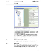
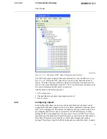
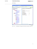
Fig. 4.3.-1 shows an example view of the COM 610 Communication Engineering
Tool (CET) including an object tree in the Communication structure on the left and
property grid window displaying the object properties on the right.

