Page 14
© 2023 ABB. All rights reserved.
CC1600SC55_QSG
Rev 4.0
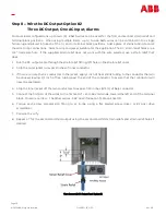
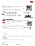
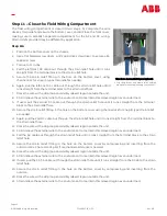
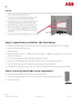
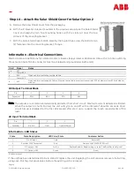
Step 14 –
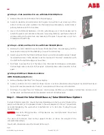
Attach the Solar Shield Cover for Solar Option 2
A.
Remove the Solar Shield Cover from the packaging.
B.
With the
5”
Elevation bracket mounted in the previous setup, take the Solar Shield
Cover and align the two top mounting hooks with the slots cut near the top
corners of the mounting bracket.
C.
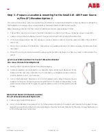
With the Solar Shield Cover held in place by the top latches, screw the bottom two
(2) fasteners into the mounting bracket. Torque
Pin #
Signal
Notes
1
-
4
N/C
5
Comm RFA
6
RFA
Open on Alarm indicating rectifier failure.
7
Comm ACF
8
ACF
Open on Alarm indicating AC failure. Must be fast as radio must resolve and relay ACF as distinct from RFA in holdover
window.
Pin
1
2
3
4
Potential
RTN
-
48V
RTN
-
48V
DC Output Terminal Block
Information –
Electrical Connections
Alarm Closure pin definitions for isolated contact closures (relays rated at 60Vdc and 0.5A with 3 to 5 ms switching
times. Note: Shell of RJ
-
45 connector must be shielded and grounded at both ends.)
Note: The outputs are common and electrically protected from short circuit. Maximum current delivered is limited.
When the output is short circuited, the unit will cycle on and off with a interval of about 14 seconds. Short
circuit hiccup is disabled for the first 20 seconds after start up to support the inrush requirements of the
load.
AC Input Terminal Block
Pin
1
2
3
Potential
Ground
Line 1
Line 2/Neutral
Information –
LED States
State
State Description
LED Color/State
Customer Action
1
No AC Input
Dark
Restore AC
2
Rectifier FAULT asserted
Red
Replace the CC1600
-
SC55 Unit*
3
DC output < 38V
Yellow
Replace Radio or Repair wiring to radio. The Rectifier is still good.
4
DC Output >38V
Green
Good
*Unit Replacement
If the unit has been determined to be in state #2 replace the unit. Replacing the unit requires removal of all wiring,
using Lock
-
Out Tag
-
Out procedures, before the existing unit is removed.


