


Belted Drive
Motor slide bases or rails, when used, must be securely anchored to the foundation with
the proper bolts. The motor shaft and the load shaft must be parallel and the sheaves
aligned. For V-belt drive, mount the sheave pulley close to the motor housing. Allow
clearance for end to end movement of the motor shaft. Do not overtighten belts as this
may cause premature bearing failure or shaft breakage.
Coupled Drive
Machines should be carefully aligned and the shaft should rotate freely without binding.
Standard EC Titanium Motors will operate successfully mounted on the floor, wall or
ceiling, and with the shaft at any angle from horizontal to vertical. Special mountings
may have duty or thrust demands that may require a different bearing system.
Flange Mount
Machines should be properly seated and aligned. Note: If improper rotation direction is
detrimental to the load, check rotation direction prior to coupling the load to the motor
shaft.
LIFTING PROVISIONS
The EC Titanium motors provided in 180 and 210 frames are provided with lifting
provisions. Always lift the motor by the lifting bolt eye or lugs provided. 140 Frame
Motors do not require lifting provisions and can be set in place manually. (2) Lifting Lugs
are provided on Top Drive Units that are offset to balance the motor weight.
Caution: Do not lift the motor and its driven load by the motor lifting hardware.
The motor lifting hardware is adequate for lifting only the motor. Disconnect the
driven load from the motor shaft before lifting the motor.
Caution: Do not lift the motor by the shaft. The motor is designed to drive a load
but it is not intended to have lifting forces and stresses applied to the motor
shaft. Damage to the motor may result
Caution: If eye bolts are used for lifting a motor, be sure they are securely
tightened. The lifting direction should not exceed a 20° angle from the shank of
the eye bolt or lifting lug. Excessive lifting angles can cause damage.
Single Lifting Bolt
Dual Offset Lifting Bolts
180, 210 Frames EC
Motors
20” maximum angle
180, 210 Frames EC Motor & Axial Units
IP (Ingress Protection)
IP designations include two numerals, the first characteristic numeral is for ingress
solid bodies and from dust. The second for ingress protection from liquid - water. EC
Titanium Motors are marked IP54 for general protection from dust and splashing water
when mounted horizontally. Other orientations such as shaft up or down may require
additionally sealing, contact the local ABB District Office to review non-horizontal
mounting requirements and ingress protection.
GUARDING
After motor installation is complete, a guard of suitable dimensions must be constructed
and installed around the motor/gearmotor. This guard must prevent personnel from
coming in contact with any moving parts of the motor or drive assembly but must allow
sufficient cooling air to pass over the motor. If a motor mounted brake is installed,
provide proper safeguards for personnel in case of brake failure. Brush inspection
plates and electrical connection cover plates or lids, must be installed before operating
the motor.
STARTING
Before starting motor remove all unused shaft keys and loose rotating parts to prevent
them from flying off. Check direction of rotation before coupling motor to load.
The motor should start quickly and run smoothly and with little noise. If the motor
should fail to start the load may be too great for the motor, the voltage is low or the
motor has been miss-wired. In any case immediately shut motor off and investigate the
cause.
ROTATION
To reverse the direction of rotation, disconnect and lockout power and interchange
any two of the three AC power leads for three phase motors. For two-phase four wire,
disconnect and lockout power and interchange the AC line leads on any one phase. For
two phase three wire, disconnect and lockout power and interchange phase one and
phase two AC line leads.
Lubrication Information
EC Titanium Motors use double-shielded sealed bearings and do not require re-
lubrication. Non−regreaseable motors when not in normal operation, should have
the motor shaft rotated 15 times to redistribute the grease within the bearing every 3
months or more often.
ELECTRICAL INSTALLATION
Flying Leads
Motors with flying lead construction must be properly terminated, connected with bolt,
lock washer and nut and wrapped with two full layers of electrical grade tape or heat
shrink tubing.
Bypass Mode
All EC Titanium AC motors are inverter duty motors using optimum pole design. They
are not intended to be used in bypass mode (across the line). Consult your ABB District
Office to determine suitability of motor for specific applications in bypass mode.
Permanent magnet motors cannot be run in bypass mode.
WARNING: Do not touch electrical connections before you first ensure that power
has been disconnected. Electrical shock can cause serious or fatal injury. Only
qualified personnel should attempt the installation, operation and maintenance of
this equipment.
WARNING: Surface temperatures of motor enclosures may reach temperatures
which can cause discomfort or injury to personnel accidentally coming into
contact with hot surfaces. Protection should be provided by the user to protect
against accidental contact with hot surfaces. Failure to observe this precaution
could result in bodily injury.
WARNING: The Adjustable Speed Controller may apply hazardous voltages to
the motor leads after power to the controller has been turned off. Verify that the
controller is incapable of delivering hazardous voltages and that the voltage at
the motor leads is zero before proceeding. Failure to observe this precaution may
result in severe bodily injury or death.
Caution: Use only a shielded motor power cable with a complete circumferential
braided or copper film/tape ground jacket around the power leads. This ground
should be secured to the motor frame from within the motor terminal box and
must return without interruption to the drive ground. In addition, if the motor and
coupled equipment are not on a single common metal base plate, it is important
to equalize the equipment ground potentials by bonding the motor frame to the
coupled equipment using a high frequency conductor such as a braided strap.
Note: Main power leads for CE Marked Motors may be marked U, V, W – for
standard configurations, please consult connection diagrams.
1. Single Voltage/Three Lead Motors. Connect leads marked U/T1, V/T2 and W/T3 to
the appropriate control output terminals (refer to the Controller Instruction Manual).
See Figure 1-1.
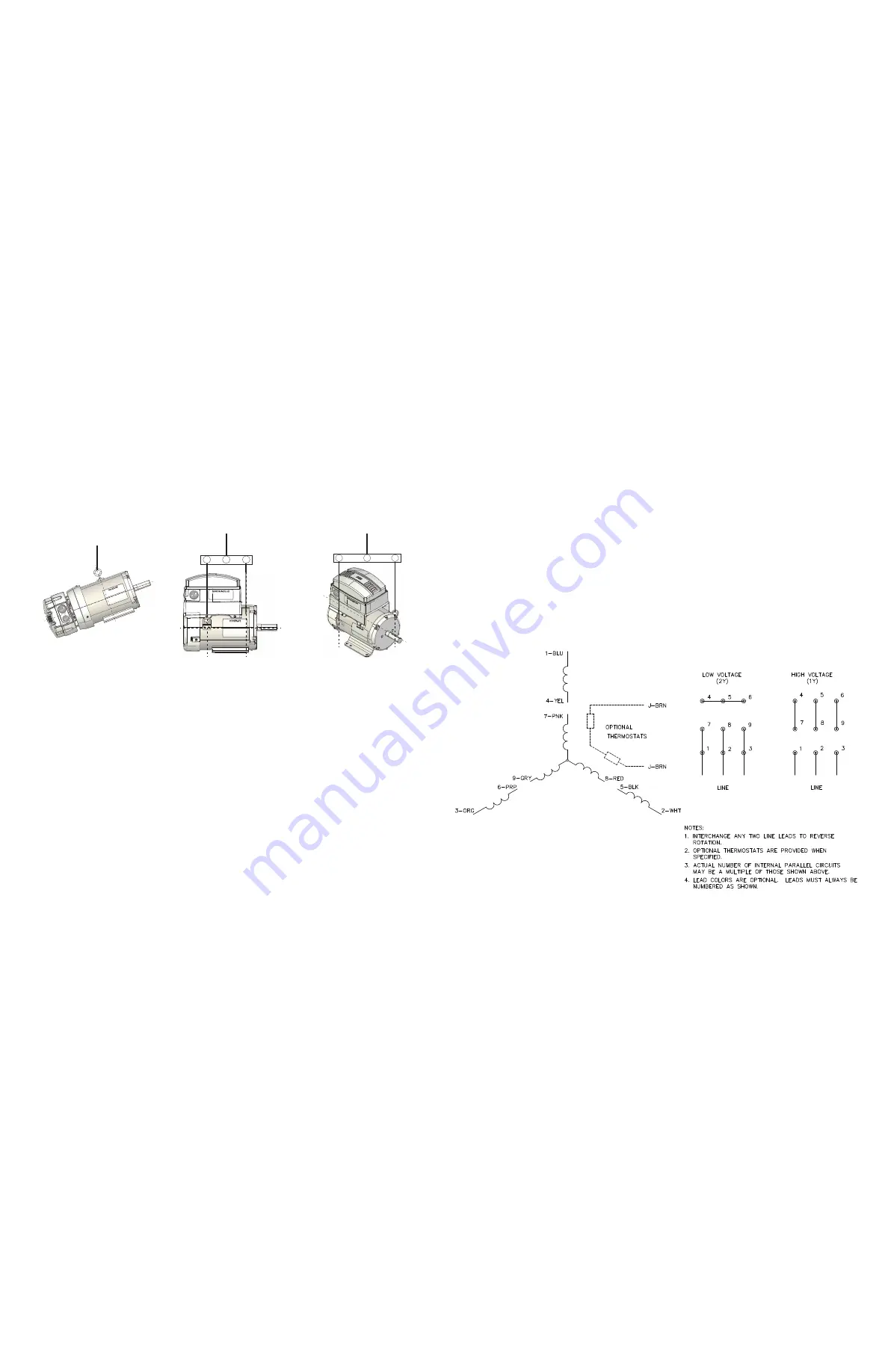
2. Dual Voltage Motors
Be sure the motor leads are connected properly for “Low” or “High” voltage connection,
see Figure 1-1.
Connect leads marked U/T1, V/T2 and W/T3 to the appropriate control output terminals
(refer to the Controller Instruction Manual).
For motors supplied with temperature protection, leads P1 & P2 are thermostat leads.
They are to be connected in series with the holding coil of the motor controller, which
uses a manual momentary start switch. These are not standard with stock EC Titanium
motors.
Figure 1-1 Connection Diagram


