


44
…6
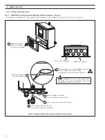
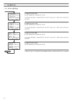
INSTALLATION
5
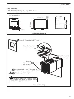
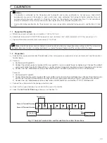
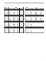
Place the blade of a small, flat bladed screwdriver
into the knockout groove and tap the
screwdriver smartly to remove the knockout
Smooth the edges of the hole
with a small round or half round file.
Fit an 'O' ring seal to the the cable gland
Insert the cable gland into the hole
in the analyzer case from the outside
Secure the cable gland
with the securing nut
2
3
4
6
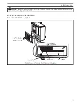
Cable entry knockouts
Factory-fitted cable gland
1
Release the captive
screws and remove
the terminal cover plate
Fig. 6.7 Cable Entry Knockouts, Wall-/Pipe-mount Analyzer
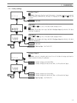
…6.3
Connections, General
6.3.2
Cable Entry Knockouts, Wall-/Pipe-mount Analyzer – Fig. 6.7
The analyzer is supplied with 7 cable glands, one fitted and six to be fitted, as required, by the user – see Fig. 6.7.
Caution.
When removing knockouts,
take great care not to damage wiring and
components within the analyzer.


