Parameters and firmware blocks
266
Group
92 RESOLVER CONF
Resolver configuration; used when parameter
is set to
.
The optional FEN-21 Resolver Interface module is compatible with resolvers which
are excited by sinusoidal voltage (to the rotor winding) and which generate sine and
cosine signals proportional to the rotor angle (to stator windings).
Note:
Configuration data is written into the logic registers of the adapter once after
the power-up. If parameter values are changed, save values into the permanent
memory by parameter
. The new settings will take effect when
the drive is powered up again, or after re-configuration is forced by parameter
Resolver autotuning is performed automatically whenever the resolver input is
activated after changes to parameters
. Autotuning must be forced after any changes in the resolver cable
connection. This can be done by setting either
to its already existing value, and then setting parameter
to 1.
If the resolver (or absolute encoder) is used for feedback from a permanent magnet
motor, an Autophasing ID run should be performed after replacement or any
parameter changes. See parameter
and section
on page
See also parameter group
on page
, and
FEN-21 Resolver Interface User’s
Manual
(3AFE68784859 [English]).
92
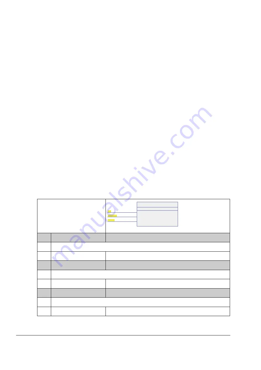
Firmware block:
RESOLVER CONF
(92)
This block configures the resolver
connection.
92.01
RESOLV POLEPAIRS
(see above)
Selects the number of pole pairs.
1…32
Number of pole pairs.
92.02
EXC SIGNAL AMPL
(see above)
Defines the amplitude of the excitation signal.
4.0…12.0 Vrms
Excitation signal amplitude.
92.03
EXC SIGNAL FREQ
(see above)
Defines the frequency of the excitation signal.
1…20 kHz
Excitation signal frequency.
RESOLVER CONF
40
TLF11 10 msec
(3)
92.01 RESOLV POLEPAIRS
[ 1 ]
92.02 EXC SIGNAL AMPL
[ 4.0 Vrms ]
92.03 EXC SIGNAL FREQ
[ 1 kHz ]
Summary of Contents for ACSM1 Series
Page 1: ...ABB motion control drives Firmware manual ACSM1 motion control program ...
Page 4: ......
Page 34: ...Drive programming using PC tools 34 ...
Page 86: ...Drive control and features 86 ...
Page 265: ...Parameters and firmware blocks 265 1 100 us 100 µs 2 1 ms 1 ms 3 50 ms 50 ms ...
Page 302: ...Parameter data 302 ...
Page 422: ...Application program template 422 ...
Page 430: ...Appendix A Fieldbus control 430 ...
Page 500: ...Appendix D Application examples 500 ...
Page 508: ...Appendix E Control chain and drive logic diagrams 508 ...
Page 510: ...3AFE68848270 REV H EN 2015 06 26 Contact us www abb com drives www abb com drivespartners ...


