


Parameters 265
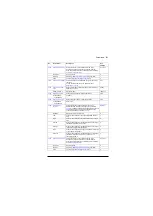
Defines the warning limit for temperature monitoring
function 1. When measured temperature 1 exceeds this
limit, a warning (
) is generated.
The unit is selected by parameter
Note: With a PTC sensor, the unit is ohms.
110 °C or
230 °F
-60…5000 °C or
ohm, or -76…9032 °F
Warning limit for temperature monitoring function 1.
1 = 1 unit
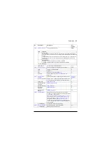
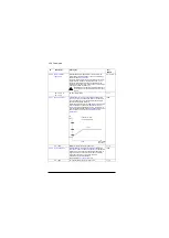
Specifies the analog input when the setting of
requires measurement through an
analog input.
Note:
If the input is located on an I/O extension module,
use the selection
to point to the AI actual value in
group 14, 15 or 16, eg.
Not selected
None.
0
AI1 actual value
Analog input AI1 on the control unit.
1
AI2 actual value
Analog input AI2 on the control unit.
2
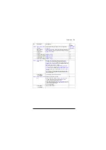
Source selection (see
on page
).
-
Selects the source from which measured temperature 2 is
read.
Usually this source is from a sensor connected to the
motor controlled by the drive, but it could be used to
measure and monitor a temperature from other parts of the
process as long as a suitable sensor is used as per the
selection list.
Disabled
None. Temperature monitoring function 2 is disabled.
0
Estimated
temperature
Estimated motor temperature (see parameter
The temperature is estimated from an internal drive
calculation. It is important to set up the ambient
temperature of the motor in
1
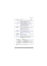
KTY84 analog I/O
KTY84 sensor connected to the analog input selected by
parameter
and an analog
output. The input and output can be on the drive control
unit or on an extension module.
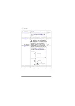
The following settings are required:
• Set the hardware jumper or switch related to the analog
input to
U
(voltage). Any change must be validated by a
control unit reboot.
• Set the unit selection parameter of the input to volt.
• Set the source selection parameter of the analog output
to “
• Select the analog input in parameter
. In case the
input is located on an I/O extension module, use the
selection
to point at the actual input value
parameter (for example,
).
The analog output feeds a constant current through the
sensor. As the resistance of the sensor changes along with
its temperature, the voltage over the sensor changes. The
voltage is read by the analog input and converted into
degrees.
2
No.
Name/Value
Description
Def/
FbEq16
Summary of Contents for ACS880 ESP
Page 1: ...ABB industrial drives Firmware manual ACS880 PCP ESP control program ...
Page 4: ......
Page 28: ...28 PCP ESP control start up ...
Page 30: ...30 Using the control panel ...
Page 94: ...94 Standard programposi features ...
Page 100: ...100 Default control connections ...
Page 360: ...360 Parameters ...
Page 436: ...436 Fault tracing ...
Page 486: ...486 Control chain diagrams ...
Page 492: ...492 Appendix ESP with step up transformer and sine filter ...
Page 494: ...Contact us www abb com drives www abb com drivespartners 3AXD50000016186 Rev B EN 2015 10 27 ...


