224 Parameters
42.14
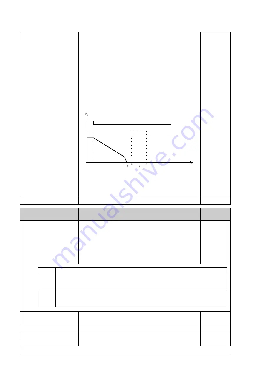
Extend run time
Defines an extended run time for the brake control function at
stop. During the delay, the motor is kept magnetized
(modulating) and ready for an immediate restart.
0.0 s = Normal stop routine of the brake control function: The
motor magnetization (modulation) is switched off after the
brake close delay has passed.
0.1…3600.0 s = Extended stop routine of the brake control
function: The motor magnetization (modulation) is switched
off after the brake close delay and the extended run time have
passed. During the extended run time, a zero torque
reference is applied, and the motor is ready for an immediate
restart.
0.0 … 3600.0 s
Extended run time.
100 = 1 s
44
44 Maintenance
Maintenance counter configuration. See also section
on page
.
44.01
Ontime1 func
Configures on-time counter 1. This counter runs whenever
the signal selected by parameter
is on.
After the limit set by parameter
is
reached, an alarm specified by parameter
is given, and the counter reset.
The current value of the counter is readable from parameter
. Bit 0 of
indicates that the count has exceeded the limit.
44.02
Ontime1 src
Selects the signal to be monitored by on-time counter 1. See
parameter
.
RO1
Relay output RO1 (as indicated by
1073742338
Running
Bit 3 of
(see page
).
1073939969
Charged
Bit 9 of
(see page
).
1074333186
No.
Name/Value
Description
FbEq
t
t
1
2
3
Start/stop
1 = Brake close speed
2 = Brake close delay
3 = Extended run time
Drive modulating
Actual speed
Bit
Function
0
Counter mode
0 = Loop: If alarm is enabled by bit 1, the alarm stays active only for 10 seconds.
1 = Saturate: If alarm is enabled by bit 1, the alarm stays active until reset.
1
Alarm ena (Alarm enable)
0 = Disable: No alarm is given when limit is reached.
1 = Enable: Alarm is given when limit is reached.
Summary of Contents for ACS850 series
Page 1: ...ACS850 Firmware Manual ACS850 Standard Control Program ...
Page 4: ......
Page 56: ...56 Control locations and operating modes ...
Page 262: ...262 Parameters ...
Page 310: ...310 Fault tracing ...
Page 348: ...348 Control through a fieldbus adapter ...
Page 358: ...358 Drive to drive link ...


