


28
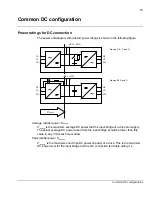
Common DC capacitance
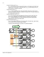
Many acceleration and deceleration processes are typical for applications with high
performance machinery drives. It is useful for such applications to connect those drives
into the common DC link to utilize also the DC link energy storage behavior. In the
common DC system, all the capacitor banks of the individual drive modules are
connected in parallel and they act as a common energy storage. This provides the
following advantages:
•
The need for the braking resistor in the drive system may be eliminated. The heat
dissipation in the control cabinet is considerably reduced.
•
The energy stored in the DC bus capacitors during the regenerating can be used
afterwards for the motoring power. The energy demand from the supply is then
reduced.
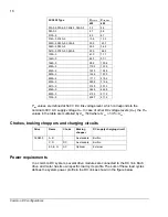
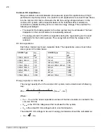
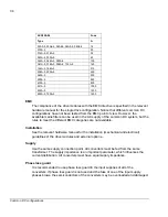
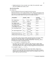
DC link capacitance
Each drive module has its own capacitor bank. The capacitance value of each drive
size is given in the table below.
C
dc
C
dc
ACS850 Type
µ
F
ACS850 Type
µ
F
03A0-5, 03A6-5
120
103A-5
2400
04A8-5, 06A0-5,
240
144A-5
3600
010A-5 370 166A-5,
202A-5
4700
014A-5, 018A-5
740
225A-5, 260A-5, 290A-5
7050
025A-5, 030A-5,
670
430A-5
8600
044A-5, 050A-5
1000
521A-5
10800
061A-5 1340
602A-5
12900
078A-5, 094A-5
2000
693A-5, 720A-5
15100
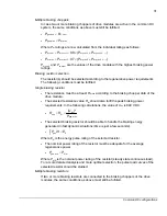
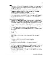
Energy capacity in common DC
The energy capacity
W
dc
in the common DC system can be determined in following
way:
(
)
(
)
2
2
3
2
1
2
dc
lim
,
dc
dcn
dc
dc
dc
DC
U
U
C
...
C
C
C
W
−
×
+
+
+
+
=
Where:
•
C
dc1
…
C
dcn
are the actual capacitance values of the drive modules connected to the
common DC link.
•
U
dc,lim
is the DC link voltage level that is allowed for the system.
•
U
dc
is the actual DC link voltage level in a normal situation.
The actual DC link voltage to be used in energy calculations should be calculated as:
•
ac
dc
U
U
×
=
2
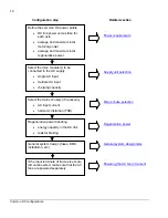
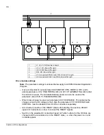
Common DC configurations
Summary of Contents for ACS850 series
Page 1: ...ACS850 Common DC configuration application guide...
Page 2: ......
Page 4: ......
Page 6: ...6 Safety instructions...
Page 9: ...9 Table of contents...
Page 11: ...11 Introduction to the manual...


