


Guidelines for planning the electrical installation 53
Additional data for calculating the rise time and the peak line-to-line voltage
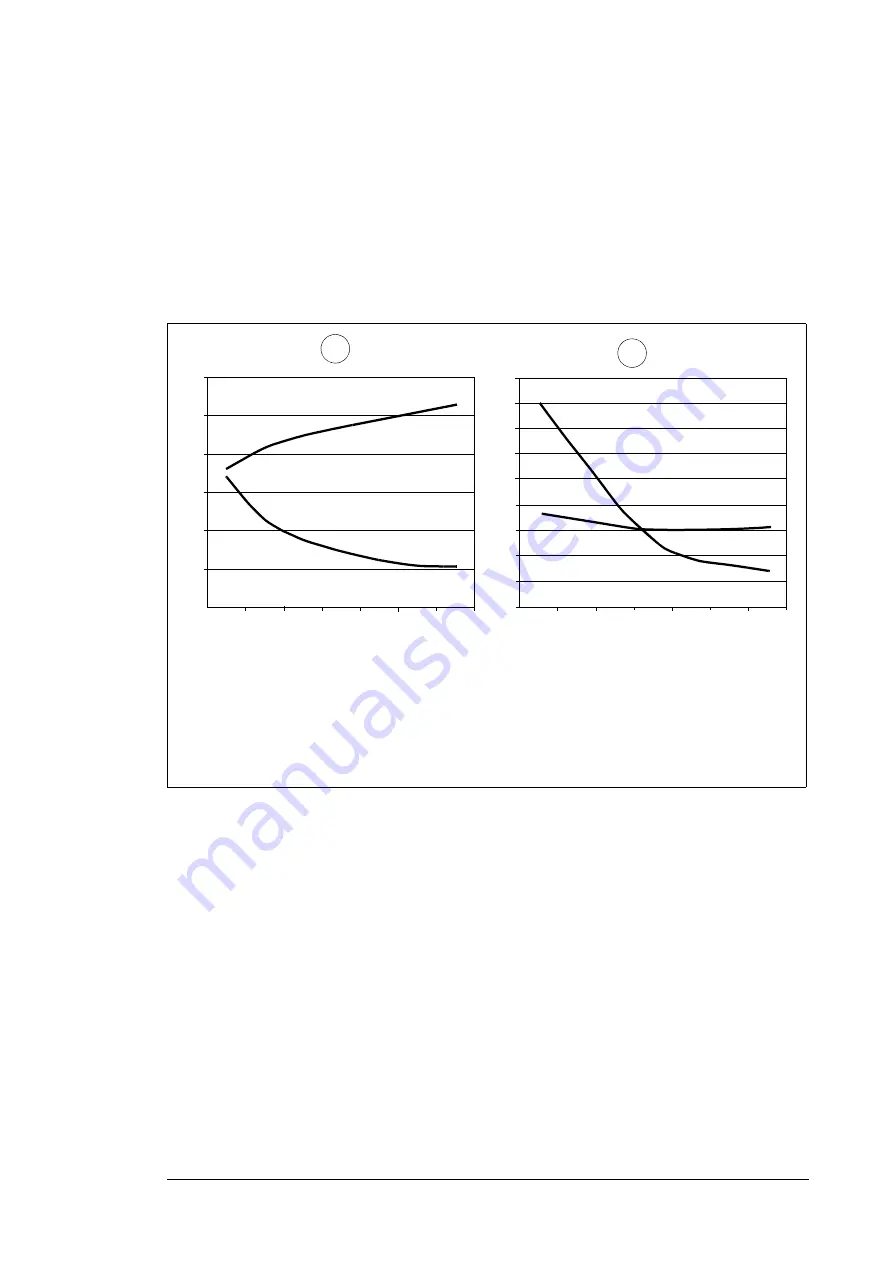
If you need to calculate the actual peak voltage and voltage rise time considering the
actual cable length, proceed as follows:
•
Peak line-to line voltage: Read the relative
Û
LL
/
U
N
value from the appropriate diagram
below and multiply it by the nominal supply voltage (
U
N
).
•
Voltage rise time: Read the relative values
Û
LL
/
U
N
and (du/dt)/
U
N
from the appropriate
diagram below. Multiply the values by the nominal supply voltage (
U
N
) and substitute
into equation
t
= 0.8 ·
Û
LL
/(du/dt).
Additional note for common mode filters
The drive is equipped with a common mode filter as standard.
Selecting the power cables
General rules
Select the input power and motor cables according to local regulations:
•
Select a cable capable of carrying the drive nominal current. See section
(page
) for the rated currents.
•
Select a cable rated for at least 70 °C maximum permissible temperature of conductor
in continuous use.
•
Make sure that the inductance and impedance of the PE conductor/cable (grounding
wire) is rated according to permissible touch voltage appearing under fault conditions
(so that the fault point voltage will not rise excessively when a ground fault occurs).
•
600 V AC cable is accepted for up to 500 V AC.
A
Drive with du/dt filter
B
Drive without du/dt filter
I
Motor cable length
Û
LL
/
U
N
Relative peak line-to-line voltage
(du/dt)/U
N
Relative du/dt value
Note
:
Û
LL
and du/dt values are approximately 20% higher with resistor braking.
Û
LL
/
U
N
l
(m)
du/dt
UN
-------------(1/
s)
1.0
2.0
5.0
4.0
3.0
1.5
2.5
3.5
4.5
100
200
300
100
200
300
0.0
0.5
1.0
1.5
2.0
2.5
3.0
l
(m)
du/dt
UN
-------------(1/
s)
Û
LL
/
U
N
5.5
A
B
Summary of Contents for ACS580-07-0495A-4
Page 1: ...ABB general purpose drives Hardware manual ACS580 07 drives 250 to 500 kW ...
Page 4: ......
Page 8: ...4 Update notice ...
Page 16: ...12 ...
Page 24: ...20 Safety instructions ...
Page 42: ...38 Operation principle and hardware description ...
Page 74: ...70 Electrical installation PE PE 8 PE 13 11 7 8 12 13 ...
Page 82: ...78 Electrical installation ...
Page 102: ...98 Fault tracing ...
Page 114: ...110 Maintenance R10 and R11 4 5 2 7 6 3 8 ...
Page 115: ...Maintenance 111 R10 and R11 9 10 ...
Page 116: ...112 Maintenance R10 and R11 11 ...
Page 117: ...Maintenance 113 R10 and R11 12b 12a ...
Page 118: ...114 Maintenance R10 and R11 R10 and R11 17 14 13 R11 15 16 ...
Page 134: ...130 Technical data ...
Page 137: ...Dimension drawings 133 13 Dimension drawings Example dimension drawings are shown below ...
Page 138: ...134 Dimension drawings Frames R10 and R11 IP42 ...
Page 139: ...Dimension drawings 135 Frames R10 and R11 IP54 option B055 ...
Page 140: ...136 Dimension drawings ...
Page 152: ...148 Safe torque off function ...
Page 174: ...Contact us www abb com drives www abb com drivespartners 3AXD50000032622 Rev A EN 2016 03 16 ...


