


222 Actual signals and parameters
20 LIMITS
Drive operation limits.
Speed values are used in vector control and frequency
values are used in scalar control. The control mode is
selected by parameter
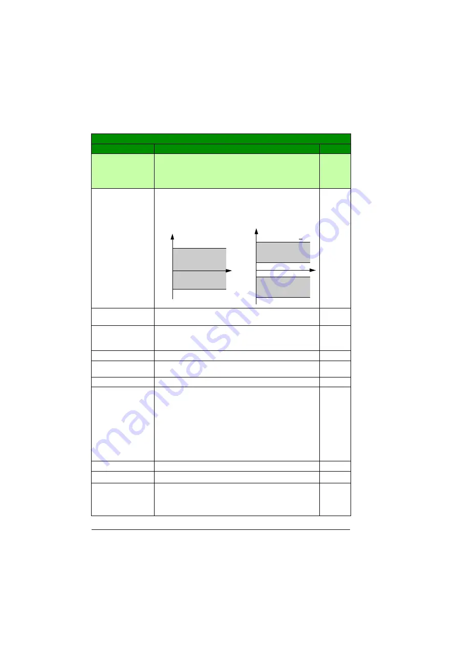
2001 MINIMUM
SPEED
Defines the allowed minimum speed.
A positive (or zero) minimum speed value defines two
ranges, one positive and one negative.
A negative minimum speed value defines one speed range.
0rpm
-30000…
30000 rpm
Minimum speed
1 = 1 rpm
2002 MAXIMUM
SPEED
Defines the allowed maximum speed. See parameter
.
E: 1500 rpm
/
U: 1800rpm
0…30000 rpm
Maximum speed
1 = 1 rpm
2003 MAX
CURRENT
Defines the allowed maximum motor current.
1.8 ·
I
2N
A
0.0…1.8 ·
I
2N
A Current
1 = 0.1 A
2005 OVERVOLT
CTRL
Activates or deactivates the overvoltage control of the
intermediate DC link.
Fast braking of a high inertia load causes the voltage to rise
to the overvoltage control limit. To prevent the DC voltage
from exceeding the limit, the overvoltage controller
automatically decreases the braking torque.
Note:
If a brake chopper and resistor are connected to the
drive, the controller must be off (selection
) to
allow chopper operation.
DISABLE
Overvoltage control deactivated
0
ENABLE
Overvoltage control activated
1
EN WITH
BRCH
Both braking chopper and overvoltage controller are
enabled so that the braking chopper capability is used to its
maximum and the overvoltage controller is activated above
that.
2
All parameters
No.
Name/Value
Description
Def/FbEq
0
Speed
value is < 0
value is > 0
0
-(
)
-(
)
t
t
Allowed
speed range
Allowed
speed range
Allowed
speed range
Speed
Summary of Contents for ACS355 series
Page 1: ...ABB machinery drives User s manual ACS355 drives ...
Page 4: ......
Page 16: ...16 ...
Page 32: ...32 Operation principle and hardware description ...
Page 58: ...58 Electrical installation ...
Page 74: ...74 Start up control with I O and ID run ...
Page 106: ...106 Control panels ...
Page 120: ...120 Application macros ...
Page 178: ...178 Program features ...
Page 338: ...338 Fieldbus control with embedded fieldbus ...
Page 368: ...368 Fault tracing ...
Page 404: ...404 Dimension drawings ...
Page 410: ...410 Appendix Resistor braking ...
Page 434: ...434 Appendix Permanent magnet synchronous motors PMSMs ...


