


122
ACS 400 User’s Manual
8119
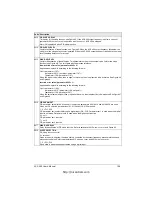
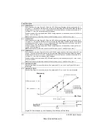
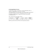
AUTOCHNG LEVEL
Sets the operation limit for the Autochange logic. This parameter can be used to deny Autochange when the
Pump-Fan system is operating near maximum capacity. When the output from the PID/PFC control block
exceeds the level set by this parameter, Autochange operation is not possible.
Figure 51 Autochange level.
Autochange operation
The purpose of the Autochange operation is to ensure equal duty time for all the motors. Each motor in the
system will in its turn be connected to the ACS 400 as well as direct on line. The starting order of the motors
is changed when Autochange is done.
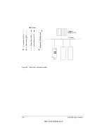
To use the Autochange function, an external alternation switchgear is needed. Refer to “Appendix B” on
page 157 for more information. When Autochange is used, the interlocks (parameter 8120) must also be
taken into use.
The Autochange is performed when the Autochange Interval (parameter 8118) is elapsed from the previous
autochange and the output from the PFC is below the level set by this parameter.
Autochange operation is as follows:
1. The speed controlled motor stops. The contactor of the speed controlled motor is switched off.
2. The starting order is changed (the starting order counter steps onward).
3. The contactor of the motor that will be the new speed controlled motor is switched off (if the motor is
running). If other motors are running, they will not be interrupted.
4. The contactor of the new speed controlled motor is switched on. The autochange switchgear connects
this motor to the ACS 400.
5. Time set with parameter 8122
PFC
START
DELAY
is waited.
6. Speed controlled motor starts. If a constant speed motor was stopped in Step 3, one more motor is
connected direct on-line by switching on the contactor of that motor. After this step the same number of
motors is running as before the Autochange.
7. Normal PFC operation continues.
As an example, the starting order in a three motor system is changed as follows:
First start: Motor no. 1, motor no. 2, motor no. 3.
Second start: Motor no. 2, motor no. 3, motor no. 1.
Third start: Motor no. 3, motor no. 1, motor no. 2. (etc...)
If some motors in the system are interlocked, the Autochange logic skips them. If all interlocks are active
and no motor can be started, an interlock alarm (Alarm 30) is displayed.
Note! The ACS 400 always coasts to stop when autochange is performed.
Note! Autochange can also occur during PID sleep.
Note! When the ACS 400’s power supply is switched off, the values of the starting order counter and
Autochange Interval counter are stored in the permanent memory. The counters continue from the stored
values after the power supply is switched on again.
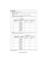
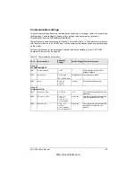
Code Description
No aux
1 aux
motor
2 aux
motors
motors
PID output
8119
AUTOCHNG
LEVEL
100 %
Output frequency
f
MAX
Allowed autochange area
http://nicontrols.com
Summary of Contents for ACS 400
Page 3: ...http nicontrols com ...
Page 5: ...http nicontrols com ...
Page 7: ...iv ACS 400 User s Manual http nicontrols com ...
Page 45: ...34 ACS 400 User s Manual http nicontrols com ...
Page 52: ...ACS 400 User s Manual 41 Motor Will Not Run http nicontrols com ...
Page 53: ...42 ACS 400 User s Manual Motor Stalls during Acceleration http nicontrols com ...
Page 54: ...ACS 400 User s Manual 43 Overvoltage Fault Indication http nicontrols com ...
Page 55: ...44 ACS 400 User s Manual Overcurrent Fault Indication http nicontrols com ...
Page 56: ...ACS 400 User s Manual 45 Overload Fault Indication http nicontrols com ...
Page 57: ...46 ACS 400 User s Manual Undervoltage Fault Indication http nicontrols com ...
Page 58: ...ACS 400 User s Manual 47 External Fault Indication http nicontrols com ...
Page 59: ...48 ACS 400 User s Manual No Operator Display http nicontrols com ...
Page 75: ...64 ACS 400 User s Manual http nicontrols com ...
Page 161: ...150 ACS 400 User s Manual http nicontrols com ...
Page 167: ...156 ACS 400 User s Manual http nicontrols com ...
Page 177: ...166 ACS 400 User s Manual http nicontrols com ...
Page 179: ...168 ACS 400 User s Manual ACS 400 NEMA Type 1 Enclosure R2 Frame Size http nicontrols com ...
Page 180: ...ACS 400 User s Manual 169 ACS 400 NEMA Type 1 Enclosure R3 Frame Size http nicontrols com ...
Page 181: ...170 ACS 400 User s Manual ACS 400 NEMA Type 1 Enclosure R4 Frame Size http nicontrols com ...
Page 182: ...ACS 400 User s Manual 171 ACS 400 NEMA Type 12 4 Enclosure R1 Frame Size http nicontrols com ...
Page 183: ...172 ACS 400 User s Manual ACS 400 NEMA 12 4 Enclosure R2 Frame Size http nicontrols com ...
Page 184: ...ACS 400 User s Manual 173 ACS 400 NEMA Type 12 4 R3 Frame Size http nicontrols com ...
Page 185: ...174 ACS 400 User s Manual ACS 400 NEMA Type 12 4 R4 Frame Size http nicontrols com ...
Page 186: ...http nicontrols com ...