


ACS 400 User’s Manual
119
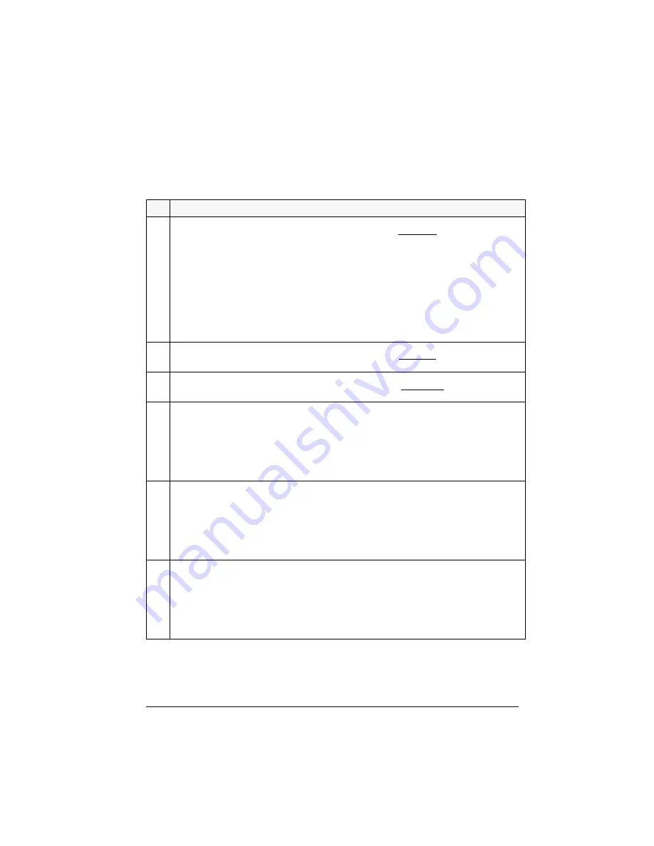
Group 81: PFC Control
Parameters for Pump-Fan Control (PFC). “Appendix B” on page 157 gives detailed information on
PFC. “Application Macros” on page 53 describes the default signal connections.
Code Description
8103
REFERENCE STEP 1
Sets a percentage value that is added to the process reference when at least one auxiliary (constant speed)
motor is running. Default value is 0 %.
Example:
An ACS 400 operates three parallel pumps that pump water to a pipe. The pressure in the pipe is
controlled. The constant pressure reference is set by parameter 4020
INTERNAL
SETPNT
.
At low water consumption levels, only the speed regulated pump is run. When water consumption
increases, constant speed pumps are started; first one pump, and, if the demand is still growing, the other
pump.
When water flow increases, the pressure loss increases between the beginning (measurement site) and the
end of the pipe. By setting suitable reference steps (parameters 8103
REFERENCE
STEP
1 and 8104
REFERENCE
STEP
2) the process reference is increased along with the increasing pumping capacity. The
reference steps compensate the growing pressure loss and prevent the pressure drop at the end of the
pipe.
8104
REFERENCE STEP 2
Sets a percentage value that is added to the process reference when at least two auxiliary (constant speed)
motors are running. Default value is 0 %. See parameter 8103
REFERENCE
STEP
1
8105
REFERENCE STEP 3
Sets a percentage value that is added to the process reference when at least three auxiliary (constant
speed) motors are running. Default value is 0 %. See parameter 8103
REFERENCE
STEP
1.
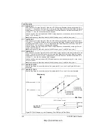
8109
START FREQ 1
Sets a frequency limit. See Figure 50 on page 120. When ACS 400 output frequency exceeds value (8109
START
FREQ
1 + 1 Hz) and no auxiliary motors are running, the Start Delay counter is started. When the time
set with parameter 8115
AUX MOT START D
is elapsed and if the output frequency is still above value (8109
START
FREQ
1 - 1 Hz), the first auxiliary motor is started.
After the first auxiliary motor is started, ACS 400 output frequency is decreased by value (8109
START
FREQ
1 - 8112
LOW
FREQ
1).
Note!
Start Frequency 1 should be within limits 8112
LOW
FREQ
1 and 2008
MAXIMUM
FREQ
-1.
8110
START FREQ 2
Sets a frequency limit (see Figure 50). When the ACS 400 output frequency exceeds value (8110
START
FREQ
2 + 1 Hz) and one auxiliary motor is running, the Start Delay counter is started. When the time set with
parameter 8115
AUX MOT START D
is elapsed and if the output frequency is still above value (8110
START
FREQ
2 - 1 Hz), the second auxiliary motor is started.
After the second auxiliary motor is started, the ACS 400 output frequency is decreased by value (8110
START
FREQ
2 - 8113
LOW
FREQ
2).
Note!
Start Frequency 2 should be within limits 8112
LOW
FREQ
2 and 2008
MAXIMUM
FREQ
-1.
8111
START FREQ 3
Sets a frequency limit (see Figure 50). When the ACS 400 output frequency exceeds the value (8111
START
FREQ
3 + 1 Hz) and two auxiliary motors are running, the Start Delay counter is started. When the time set
with parameter 8115
AUX MOT START D
is elapsed and if the output frequency is still above value (8111
START
FREQ
3 - 1 Hz), the third auxiliary motor is started.
After the third auxiliary motor is started, the ACS 400 output frequency is decreased by value (8111
START
FREQ
3 - 8114
LOW
FREQ
3).
Note!
Start Frequency 3 should be within limits 8112
LOW
FREQ
3 and 2008
MAXIMUM
FREQ
-1.
http://nicontrols.com
Summary of Contents for ACS 400
Page 3: ...http nicontrols com ...
Page 5: ...http nicontrols com ...
Page 7: ...iv ACS 400 User s Manual http nicontrols com ...
Page 45: ...34 ACS 400 User s Manual http nicontrols com ...
Page 52: ...ACS 400 User s Manual 41 Motor Will Not Run http nicontrols com ...
Page 53: ...42 ACS 400 User s Manual Motor Stalls during Acceleration http nicontrols com ...
Page 54: ...ACS 400 User s Manual 43 Overvoltage Fault Indication http nicontrols com ...
Page 55: ...44 ACS 400 User s Manual Overcurrent Fault Indication http nicontrols com ...
Page 56: ...ACS 400 User s Manual 45 Overload Fault Indication http nicontrols com ...
Page 57: ...46 ACS 400 User s Manual Undervoltage Fault Indication http nicontrols com ...
Page 58: ...ACS 400 User s Manual 47 External Fault Indication http nicontrols com ...
Page 59: ...48 ACS 400 User s Manual No Operator Display http nicontrols com ...
Page 75: ...64 ACS 400 User s Manual http nicontrols com ...
Page 161: ...150 ACS 400 User s Manual http nicontrols com ...
Page 167: ...156 ACS 400 User s Manual http nicontrols com ...
Page 177: ...166 ACS 400 User s Manual http nicontrols com ...
Page 179: ...168 ACS 400 User s Manual ACS 400 NEMA Type 1 Enclosure R2 Frame Size http nicontrols com ...
Page 180: ...ACS 400 User s Manual 169 ACS 400 NEMA Type 1 Enclosure R3 Frame Size http nicontrols com ...
Page 181: ...170 ACS 400 User s Manual ACS 400 NEMA Type 1 Enclosure R4 Frame Size http nicontrols com ...
Page 182: ...ACS 400 User s Manual 171 ACS 400 NEMA Type 12 4 Enclosure R1 Frame Size http nicontrols com ...
Page 183: ...172 ACS 400 User s Manual ACS 400 NEMA 12 4 Enclosure R2 Frame Size http nicontrols com ...
Page 184: ...ACS 400 User s Manual 173 ACS 400 NEMA Type 12 4 R3 Frame Size http nicontrols com ...
Page 185: ...174 ACS 400 User s Manual ACS 400 NEMA Type 12 4 R4 Frame Size http nicontrols com ...
Page 186: ...http nicontrols com ...