


Appendix A Hardware Units
CI852 and TP852 – FOUNDATION Fieldbus H1 Interface
3BSE 027 941 R301
159
Indicators
The CI852 FOUNDATION Fieldbus H1 interface has the following LED indicators.
Technical Data
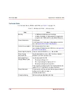
Table 41. CI852 FOUNDATION Fieldbus H1 – LED Indications
Indication/Color
Function
F(ault) /Red
Unit error detected. Controlled by Control
Software. Set and cleared by the Hardware during
controller Reset.
R(un) /Green
Operating. Controlled by the Control Software.
Cleared by the Hardware during controller Reset.
Rx/Tx /Yellow
Transmission to or from the unit.
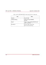
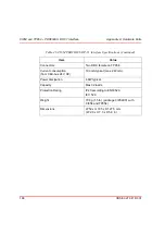
Table 42. CI852 Foundation Fieldbus Interface Specifications
Item
Description
Type
– Foundation Fieldbus H1 master and link
schedule.
– Note the complete controller has a HW
capability necessary for a Foundation Fieldbus
linking device.
Number of channels
Single channel Foundation Fieldbus H1
(31.25 kbit/s).
Protocols
Foundation Fieldbus H1 via port on CI852.
Communication speed
31.25 kbit/s (FF H1)
Allowed node address
20 – 247
Galvanic isolation
By means of transformer.
Summary of Contents for AC 800M
Page 1: ...ControlIT AC 800M Version 2 1 Controller Hardware Hardware and Operation...
Page 2: ......
Page 3: ...Controller Hardware Hardware and Operation ControlIT AC 800M Version 2 1...
Page 10: ...7DEOH RI RQWHQWV 10 3BSE 027 941 R301...
Page 20: ...Related Documentation About This Book 20 3BSE 027 941 R301...
Page 26: ...Operating Environment Safety Summary 26 3BSE 027 941 R301...
Page 42: ...Product Release History Section 1 Introduction 42 3BSE 027 941 R301...
Page 108: ...Powering from an External 24 V DC Source Section 3 Configuration 108 3BSE 027 941 R301...
Page 118: ...Verification of Redundant CPU Section 4 Operation 118 3BSE 027 941 R301...
Page 212: ...Low Voltage Directive LVD Appendix D Directive Considerations 212 3BSE 027 941 R301...
Page 214: ...Hazardous Location Approval Appendix E Standards 214 3BSE 027 941 R301...
Page 228: ...QGH 228 3BSE 027 941 R301...
Page 229: ......


