


Power Supply System
Section 3 Configuration
102
3BSE 027 941 R301
Power Supply System
The configuration of a power supply system for an AC 800M controller is very
straightforward.
Configurations
on page 106 gives a series of simple circuit diagrams showing various
possibilities for connecting the incoming mains power – via the mains breaker, the
power supply units and the SS822 voting devices – to the 24 V DC distribution
terminals.
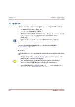
The AC 800M Controller and its I/O system are normally located in one or several
enclosures or cabinets. The cabinet housing the AC 800M Controller can also
contain I/O units connected to the controller via the electrical ModuleBus, the
optical ModuleBus or the communication interfaces for PROFIBUS DP and
PROFIBUS DP-V1.
Cabinet containing the AC 800M controller
From this cabinet power may be required for:
•
Powering Units: power to the electronic circuitry for each unit in the cabinet.
•
Powering Field Equipment: power to equipment, relay contacts etc. located
outside the cabinet, but connected to the inputs/outputs of the I/O units in the
cabinet.
It is strongly recommended to:
•
use a power supply in each cabinet for Powering Units (only when cabinets are
mounted side by side can power to the units be taken from another cabinet)
•
use separate power supplies for Powering Units and Powering Field
Equipment (see
on page 88 and
Cabinet containing I/O system
Use the recommendations given above if no other information is given in the I/O
system documentation.
Summary of Contents for AC 800M
Page 1: ...ControlIT AC 800M Version 2 1 Controller Hardware Hardware and Operation...
Page 2: ......
Page 3: ...Controller Hardware Hardware and Operation ControlIT AC 800M Version 2 1...
Page 10: ...7DEOH RI RQWHQWV 10 3BSE 027 941 R301...
Page 20: ...Related Documentation About This Book 20 3BSE 027 941 R301...
Page 26: ...Operating Environment Safety Summary 26 3BSE 027 941 R301...
Page 42: ...Product Release History Section 1 Introduction 42 3BSE 027 941 R301...
Page 108: ...Powering from an External 24 V DC Source Section 3 Configuration 108 3BSE 027 941 R301...
Page 118: ...Verification of Redundant CPU Section 4 Operation 118 3BSE 027 941 R301...
Page 212: ...Low Voltage Directive LVD Appendix D Directive Considerations 212 3BSE 027 941 R301...
Page 214: ...Hazardous Location Approval Appendix E Standards 214 3BSE 027 941 R301...
Page 228: ...QGH 228 3BSE 027 941 R301...
Page 229: ......


