


7
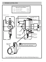
De-bubbler
Part Number
7997 500
91
150 CRS
Removable Fitting
To Fit 12 mm i.d. Tube
88
Ø6.5
Sample Outlet
Quick-release
Fittings
to Suit 12 mm
I.D. Tube
(rotatable
through 360
°
)
540
Sample Inlet
Drain Outlet
Important Note.
The de-bubbler
MUST
be mounted vertically
with the flow upwards.
Dimensions in mm
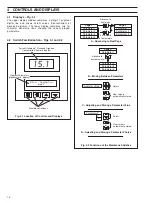
Tundish
Valve (A)
= Optional
Minimise height
to avoid syphoning
effect
Important Note.
For the high range sensor a higher
minimum flowrate is required at high turbidity levels.
1
2
Valve (B)
Flow Regulator Valve
Adjust the sample flow through the system
(0.5 to 5 l/min) using the regulating valve (B).
Open the ‘sample in’ isolating valve (A)
such that the overflow from the de-
bubbler is at a minimum.
Note.
Sample regulating
valves together with a flow indicator
are recommended to ensure easy
maintenance and consistent
performance. These devices are
not supplied with the 7320 Series
UV Organic Pollution Monitoring
system.
Important Note.
The de-bubbler
MUST
be
mounted vertically with the flow
upwards.
Tundish
Minimise height
to avoid syphoning
effect
Sample
Outlet
Connector
Sample in
Flow Regulator
Valve
De-bubbler
Drain
Outlet
7320 100
7320 000
2
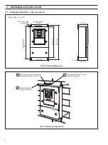
MECHANICAL INSTALLATION
Fig. 2.6 Overall Dimensions and Mounting Details of the De-bubbler
Fig. 2.7 Typical System Installation
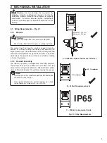
2.4
Mounting the De-bubbler – Fig. 2.6
2.4.1
Set Up Procedure for Optional De-bubbler – Fig. 2.7