


19
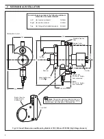
Flow-chamber
Optical
Receiver
Optical
Emitter
Wiper
Unit
Drain
Valve
Inlet/Isolating
Valve
Wiper
Blade
(parked
position)
– see inset
Seal
Seal
Locating Peg
Keyway
Locating
Peg
keyway
Wiper in
'parked'
Position
Clean the inside of the flow chamber and other
assemblies thoroughly using mild detergent and
rinse with de–ionized water.
5
Reassemble emitter and receiver modules using
new seals ensuring that the modules locate in the
keyways before tightening the collars.
6
Unscrew the collar and carefully
withdraw the module.
Unscrew the collar and
carefully withdraw the
module.
Unscrew the collar and
carefully withdraw
the module.
Perform a manual clean (see Section 5.2)
to ensure that the wiper blade is in
the 'parked' position.
Before fitting the wiper module, apply power
to the sensor and perform a manual clean
to ensure that the blade has been fitted
correctly and is orientated as shown above
when in the park position. Fit module in
flowcell as detailed in step 7.
8
Flow Chamber as
Viewed from Above
(Not to Scale)
1
2
3
4
Inspect the wiper blade for wear or damage and
fit a new one if necessary, ensuring that it is
fitted in the 'parked' position.
7
6
MAINTENANCE…
✶
Important Notes.
•
Ensure that O-rings are removed with the screw
collars; it is possible for these seals to be left inside the
flowcell.
•
During the cleaning procedure, support the modules to
remove any strain from the cables.
•
Either grub screw pins or pegs ensure that the
modules locate in only one position.
•
The emitter module is heavier than the receiver, so
extra support is needed.
Caution.
Care must be taken while handling the
emitter module and, for safety reasons, it must NEVER be
operated while outside the measurement cell.
Fig. 6.1 Low Range Sensor – Dismantling the Flowcell for Cleaning
6.2.2
Dismantling the Flowcell for Cleaning and
Wiper Maintenance – Figs 6.1 and 6.2
Caution.
The emitter and receiver modules
contain precision optical components and must be
handled accordingly. In particular, the emitter contains all
of the power supply, voltage control and lamp components
and is quite heavy. Do not support on the wires entering
the enclosure.
Always switch off the power to the instrument before
starting any service work
.
Warning.
This instrument uses a high intensity
light source which emits UV radiation and must NOT be
viewed with the naked eye. Under normal operating
conditions it is not possible to see the light source, but if
the sensor is dismantled with the power applied, it may be
possible to expose the eyes to the strobe flash.