background image


ENG  


46  


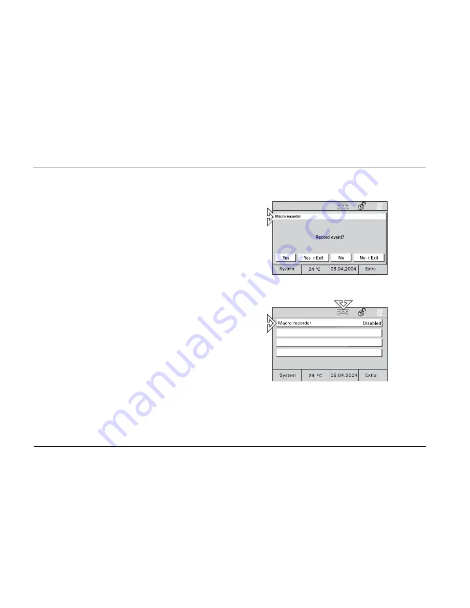
1. Activate the “Macro recorder” button by 

pressing the button for more than 3 
seconds (cassette icon on the display). 

2. Perform the switching processes to be 

recorded in the desired order. 

3. Every switching process to be recorded 

has to be confirmed with "Yes". Press the 
button "Yes+Exit" to stop the recording. 

4.  If you press the button “No” or "No+Exit", 

the switching process will not be recorded. 

  Fig. 72 

 Activation 

1. Activate the “Macro recorder” button by 

pressing the button briefly. 

Delete 

You can change macros by overwriting them. 

1. Press selected key and record switching 

processes as shown above. By pressing 
the key "No+Exit" without recording any 
processes the macro ist deletet completly. 

  Fig. 73 


Summary of Contents for 6136/30M-101

Page 1: ...ev 1 0073 1 6640 Raumpanel 6136 30M 101 6936 30M 101 Controlpanel 6136 100M 101 6936 100M 101 Controlpanel 6136 100C 101 6936 100C 101 Controlpanel 6136 100CB 101 6936 100CB 101 24 01 2006 ENG Operating Instructions ...

Page 2: ......

Page 3: ... thermostat 18 6 5 2 External room thermostats 19 6 6 Time programmes 20 6 6 1 Calling up modifying time programmes 21 6 6 2 Modifying switching times 22 6 6 3 Astro function 23 6 6 4 Setting of PIN code 25 6 7 Holiday and presence simulation 26 6 8 Lights and light scenes 28 6 8 1 Controlling light 28 6 8 2 Calling up modifying light scenes 28 6 9 Controlling blinds roller blinds 30 6 10 List of ...

Page 4: ... hand held transmitter BEO4 37 7 2 1 Switching and dimming of lamps 38 7 2 2 Calling up and saving light scenes 39 7 2 3 Switching off the consumers 39 8 Installation 40 8 1 Electric installation 40 8 2 Installation of room control panel 41 9 Software 42 9 1 Installation 42 9 2 Programming 43 ...

Page 5: ...and or disassembly A scratched screen surface will affect monitor handling Never use any hard or sharp pointed objects for entries on the touch screen monitor The screen surface may be damaged by such objects Do not spray any detergents directly on the screen surface Clean the screen using a soft cloth and commercially available glass cleaner ...

Page 6: ...umption 20VA Operating temperature 0 C to 45 C Storage 20 C to 60 C Bus connection TP Bus terminal block Room thermostat measuring range 0 C to 40 C Dimensions incl frame W x H x D 218 mm x 185 mm x 67 mm Flush mounting box Dimensions W x H x D 200 mm x 164 mm x 60 mm ...

Page 7: ...ENG 7 4 Unit view 1 Display 320 x 240 pixels 2 MMC SD card reader Fig 1 ...

Page 8: ...or groups Scope of time programmes 5 channels with 5 switching times each 20 channels with 10 switching times each 20 channels with 10 switching times each Number of alarm fault messages 10 10 10 IR channels 16 16 16 Presence simulation yes yes yes Integrated room thermostat yes yes yes Display 320 x 240 pixels Grey levels Grey levels 256 colours Message function no yes yes Info function no yes ye...

Page 9: ... the operating surface Use the supplied pen or a finger to do this Fig 2 6 2 Fundamentals The functions of the room control panel are software dependent and are determined by the saved project Thus the appearance of the operating pages varies as well Every page can be programmed individually 5 or 10 touch buttons or up to 8 icons can be displayed Fig 3 ...

Page 10: ...mmed and up to 21 operating pages in the control panels 6136 xx and 6936 xx All pages can be individually adapted to the project A reasonable page structure may e g be room oriented Fig 6 or function oriented Fig 7 It is possible to initiate switching processes directly through touch buttons depending on the programming or to call up a pop up window to initiate switching processes Fig 11 Fig 6 Fig...

Page 11: ...e unit against unauthorized or unintended use call up the main page and press on the start page title on the top left in the display for more than 3 seconds At the top right of the display the Lock symbol appears being closed The display is now safeguarded and cannot be operated any more The display is only enabled by pressing long again Fig 9 Safeguarding the display is recommended whenever the u...

Page 12: ...a new project Access to the system settings can be safeguarded by a PIN code or completely blocked When the system settings are blocked they cannot be accessed or modified by the user In this case please contact your electrician Enter your PIN code if available Fig 10 Date Set the correct date using the arrow keys Confirm your entry with OK Fig 11 ...

Page 13: ...entry with OK Fig 12 Display lighting To save energy the display lighting switches itself off automatically when the unit is not actuated Select the desired Lighting Off time from the list or disable the automatic Lighting Off function Confirm your entry with OK Fig 13 ...

Page 14: ...ider or the arrow keys Confirm your entry with OK Fig 14 Contrast Brightness Set the screen brightness and the contrast using the sliders Confirm your entry with OK Fig 15 Warning tones The warning tones are subdivided into further sub categories Alert messages Timer Alarm clock Incorrect input Keypad tones Fig 16 ...

Page 15: ...ou wish Confirm your entry with OK Fig 17 Timer Alarm clock You may select the timer alarm clock tone from the list You may also test the selected tone if you wish Confirm your entry with OK Fig 18 Incorrect input You may enable or disable the signalling tone for incorrect inputs Confirm your entry with OK Fig 19 ...

Page 16: ... Confirm your entry with OK Fig 20 Touch adjustment Adjusting the touch display will usually not be necessary Should you still go wrong frequently with your pen or your finger please adjust the touch display Fig 21 To do this point your pen exactly into the appearing target points Fig 22 ...

Page 17: ...ower supply networks e g generator mode Confirm your entry with OK Fig 24 6 5 Room thermostat climate The integrated room thermostat ensures the set climate and the desired temperature inside the room The user may modify the set room temperature and the thermostat operating mode at any time E g a nighttime temperature reduction can be activated i e the room temperature is reduced automatically at ...

Page 18: ...d room thermostat if necessary The current operating mode of the room thermostat heating cooling is shown as a symbol on the main page Fig 25 Room thermostat operating modes 1 Stand by The comfort temperature is slightly reduced 2 Comfort The set room temperature is permanently maintained 3 Nighttime temperature reduction Reduction of room temperature Fig 26 ...

Page 19: ...stats Select the Heating system button on an operating page or another button as required The operating page with the available room thermostats is opened Fig 28 Room thermostat operating modes 1 Stand by The room temperature is slightly reduced 2 Comfort The set room temperature is permanently maintained 3 Nighttime temperature reduction Reduction of room temperature Fig 29 ...

Page 20: ...led automatically using time programmes A consumer e g a lamp can be switched ON or OFF on certain days every day or during the weekend only if desired A maximum of 20 electrical units of the EIB PN system can be controlled at 5 room panel or 10 control panel different times each This allows up to 200 time functions Access to the time programmes can be completely blocked or safeguarded by a PIN co...

Page 21: ...fy the time programmes select the button displaying the date time The possible time programmes are displayed Fig 31 Select the desired time programme The possible switching times are displayed Fig 32 Select a switching time The programmed parameters are displayed Fig 33 ...

Page 22: ...ENG 22 6 6 2 Modifying switching times Setting the weekday Setting the switching time Fig 34 Fig 35 Setting the switching status Setting the switching function see chapter 6 7 Fig 36 Fig 37 ...

Page 23: ...r e g the blinds open earlier during summer than during winter To activate the astro function select the Astro Function button The Astro Function is displayed Fig 38 Enable the astro function Fig 39 Enabling Restriction of Astro settings In the first step select the Closing button and enable your selection Fig 40 ...

Page 24: ...ENG 24 In the second step select the Closing Time button and enter the desired time To enter further times go back to the switching times and select the next switching time there Fig 41 ...

Page 25: ...eas may be Modification of system settings Modification of time programmes Activation of message system 1 To modify the PIN e g select the Message system page and open the Change PIN Code menu 2 Now press the Change button Now you will be requested to enter the current PIN 3 Enter the current PIN code 4 Confirm your entry with OK and enter the new PIN code 5 Confirm your entry with OK 6 Enter the ...

Page 26: ...utdoor lights the holiday function allows setting this in the time programmes see chapter 6 6 2 First proceed as described in chapter 6 6 1 Enable the switching function as desired Fig 43 For displaying time programmes see chapter Calling up modifying time programmes To enable the holiday function select the Extra page and go to the second page Enter the date of your holiday using the arrow keys F...

Page 27: ... up to 10 units on and off during the day or opening and closing the blinds The presence simulation records the switching statuses of up to 10 units per day and stores them e g switching on of ceiling lighting in the living room at 8 00 p m on Monday All switching statuses of one week are stored To enable the presence simulation select the corresponding operating page Select Presence simulation an...

Page 28: ...e you can switch the light on and off Fig 47 6 8 2 Calling up modifying light scenes Individual light atmospheres can be called up using light scenes i e different lights are automatically set to different brightness values in a given room At the same time e g the blind or a linen is rolled down In this way individual lighting scenes for the most varied situations e g reading watching TV or for pr...

Page 29: ...a light scene Start the light scene here using the corresponding button Fig 48 Modifying and saving light scenes Start the desired light scene Now set the electric consumers so that the lighting complies with your wishes Fig 49 Save the setting by touching the corresponding button long approx 4 s The button reads Saving as a feedback Fig 50 ...

Page 30: ... To control the roller blind select e g the button Roller blind on the start page and then the corresponding button Use the arrow keys to move the blinds roller blinds up or down Press briefly to stop and adjust slats Press long to move up or down Fig 51 Control by time pro grammes For information about roller blind control by time programme see chapter Calling up modifying time programmes ...

Page 31: ...displayed in plain text with date and time Fig 52 The displayed messages remain in the foreground until they are acknowledged by a user This also applies if the reason for the alarm or the fault has meanwhile been removed and the normal condition has been restored This guarantees that an alarm or a fault will not go unnoticed An acoustic signal can indicate that there is a fault alarm see chapter ...

Page 32: ...iggers the internal alarm In addition e g an external horn or a siren can be switched on At the same time the message is displayed in the display see also List of alerts If required a message may also be transferred to a telephone interface which informs you or calls for further help by phone If a window contact of a motion detector is faulty this is indicated by a corresponding fault message see ...

Page 33: ...ivati on of message centre The operating status of the message system is shown by a symbol Fig 54 After selecting Armed or Disarmed you will be requested to enter the PIN code Fig 55 After confirming the entry with the OK button the message centre is activated or inactivated Fig 56 The PIN code can be changed only when the message centre is inactive ...

Page 34: ...ast saved information is shown Each message remains in the foreground until it is confirmed with OK or deleted with Clear A symbol indicates when an information has arrived To write an information select the Extra page and then the Infopage button The info page is displayed Fig 57 Write a note using the PDA pen or edit a saved information Fig 58 ...

Page 35: ...e is set using the Alarm clock function In both cases your attention will be drawn to the expiry of the set time by an alarm sound To set the time select the Extra page and then the Timer or Alarm clock button After setting the time enable the timer alarm clock with the Start Stop button An enabled timer or alarm clock is shown by a symbol Fig 59 ...

Page 36: ...control panels are equipped with an infrared receiver and may be remote controlled with the Busch Jaeger hand held transmitters 6010 25 and 6010 25 500 For detailed information and operating information please refer to the separate Instruction Manual of the hand held transmitter Fig 60 ...

Page 37: ...CB The IR hand held transmitter provides the following possibilities for controlling the room panel Light Modification of lighting Record Saving a light scene 0 9 Selection of lamp 1 to 10 A Selection of light scene 1 C Selection of light scene 2 D Selection of light scene 3 F Selection of light scene 4 B On or brighter E Off or darker Stop Everything off Fig 61 ...

Page 38: ... lamps according to the table below LIGHT 1 B in the table means that these three keys must be pressed one after the other not simultaneously Function Keys to be pressed Lamp 1 ON LIGHT 1 B Lamp 1 brighter LIGHT 1 B press B permanently Lamp 1 OFF LIGHT 1 E Lamp 1 darker LIGHT 1 E press E permanently Lamps 2 9 are actuated in the same way as lamp 1 Lamp 10 ON LIGHT 0 B Lamp 10 brighter LIGHT 0 B pr...

Page 39: ...means that these two keys must be pressed one after the other not simultaneously Function Keys to be pressed Call up light scene 1 LIGHT A Call up light scene 2 LIGHT C Call up light scene 3 LIGHT D Call up light scene 4 LIGHT F Save light scene 1 LIGHT LIST GO A Save light scene 2 LIGHT LIST GO C Save light scene 3 LIGHT LIST GO D Save light scene 4 LIGHT LIST GO F The key LIST must be pressed un...

Page 40: ... 8 1 Electric installation Busch Installationsbus EIB KNX connection Busch Powernet connection Fig 62 Fig 63 Do not lay energized lines behind the unit through the flush mounting box Separate the TP bus from the mains lines ...

Page 41: ...d in flush mounting box 6136 UP 1 Fit terminals to the lines 230V TP if required see chapter Connection 2 Connect terminals to the unit 3 Insert unit into flush mounting box and tighten screws Fig 64 Fig 64 4 Attach the frame and secure it using the enclosed screw Fig 65 Fig 65 ...

Page 42: ...atabase into the ETS 3 Configure the unit and set the parameters Power Projekt 4 x 1 Install the panel commissioning software from the current EIB database or from the Power Projekt CD 2 Configure the unit and set the parameters see above The EIB database can be purchased directly from Busch Jaeger or downloaded from the Internet at www busch jaeger de ...

Page 43: ...may take several hours depending on the configuration Use bus progamming only for minor project changes We recommend programming with an SD MMC card Programm ing with SD MMC card 1 Create the new project with the commissioning software on a PC and save the project on an SD MMC card 2 Insert the SD card into the room control panel and press the Read Multimedia SD card button Fig 68 Fig 67 ...

Page 44: ... automatically 5 The units exits the programming mode automatically and the basic view is displayed Fig 68 Programm ing using the bus 1 Create the new project on a PC 2 Connect the computer with the bus via an RS 232 or a USB interface 3 Press the EIB Programming Mode button and enable it Fig 69 4 Start programming from the PC This process may take several hours ...

Page 45: ...d into the control panel and press the Screensaver button Fig 70 2 Select the file from the list and press the OK button 3 Press the EIB Programming Mode button and enable it Pictures cannot be transferred through the bus Macro recorder You can use the macro recorder to record switching process in order to repeat them just like scenes as often as desired You can record and save up to 32 macros wit...

Page 46: ...irmed with Yes Press the button Yes Exit to stop the recording 4 If you press the button No or No Exit the switching process will not be recorded Fig 72 Activation 1 Activate the Macro recorder button by pressing the button briefly Delete You can change macros by overwriting them 1 Press selected key and record switching processes as shown above By pressing the key No Exit without recording any pr...

Reviews: