


LVD-EOMU02U-EN REVD 11/2022
7
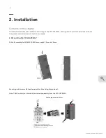
2.4 Modbus RTU Interface and wiring
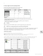
1. 2 LEDs for communication state display (TxD and RxD)
2. 2 LEDs for termination state display
3. Allocation of signal name
4. 5-pin terminal block for communication interface
Status
LEDs:
TXD - YELLOW - ON (blinking) - transmitting
RXD - YELLOW - ON (blinking) - receiving
120R - YELLOW - ON - Bus termination
PUD- YELLOW - ON - Pull up/pull down
(This VFD-GATEWAY has built in Bus Termination and Pull Up/Pull down resistors
When yellow lights are lit. bus termination resistor is activated or the pull up/pull down resistors are activated)
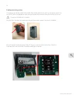
The Modbus-RTU can be connected to up to 5 ABB drives via the following connections:
Terminating resistors
120 Ω ¼ W is required at both line ends of the Modbus-RTU network
The VFD-GATEWAY has Built in 120
Ω
resistor that is enabled from the factory; the VFD-GATEWAY must be at
the beginning/end of the network at not mid-network.
The user must also turn on termination resistor at the end of line node (see specific drive manual for
information).
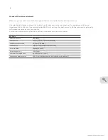
VFD Gateway
ABB Drive
Serial Interface
PIN
Signal
Terminal Pin
1
A1
Data_B, B
2
B1
Data_A, A
3
GND
GND_B, DGND, AGND
4
A2
-
5
B2
-
A1 on VFD-Gateway needs to be wired to B on VFD
B1 on VFD-Gateway needs to be wired to A on VFD


