


20 VMICPCI-7055/CPCI-7055RC Hardware Reference Manual
Publication No. 500-657055-000 Rev. G
CompactPCI Bridge Mode Default:
Normal operation mode.
Blade Mode:
In this mode the VMICPCI-7055/CPCI-7055RC will turn off the
bridge to the backplane. This allows the SBC to be inserted into any slot on the
backplane, with or without a system controller. If the SBC is inserted in a chassis
with a system controller the CPCI_RESET# will be ignored. PIGMG 2.16 will still
be available on the backplane.
CompactPCI Reset (Default):
With the jumper in installed, resets from the system
controller will always be accepted.
Reset Ignore:
With the jumper removed, a reset from the system controller will
only be accepted until the boot done LED is turned off.
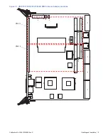
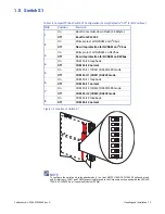
Table 1-1 Board Connectors, Headers, Switches and Jumpers
Connectors, Header,
Jumpers and Switches Function
J1, J2, J3 and J5
CompactPCI Backplane Connectors
J11, J12, J13, J14
PMC Slot 1
J21, J22, J23
PMC Slot 2
J28
LAN 0
J29
COM 0
D82
Front Panel Status Indicators
D89
Ethernet Port 2 Status LEDs
D90
Ethernet Port 1 Status LEDs
E16
Hotswap Switch Header
E18
JTAG Header
E19
Bridge Mode Jumper
E25
Reset Enable Jumper
S1
System Controller Switch
S2
Board Reset Switch
KP5
PMC Site#1 Keypin (5V VIO)
KP6
PMC Site#2 Keypin (5V VIO)
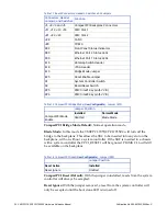
Table 1-2 CompactPCI Bridge Mode (
User Configurable
) - Jumper (E19)
Jumper Position
CompactPCI Mode
Enable
Installed
Normal Mode
Omitted
Blade Mode
Table 1-3 CompactPCI Reset (
User Configurable
) - Jumper (E25)
Jumper Position
Reset Active
Installed
Reset Ignore
Omitted


