background image

11

GENERAL OVERVIEW

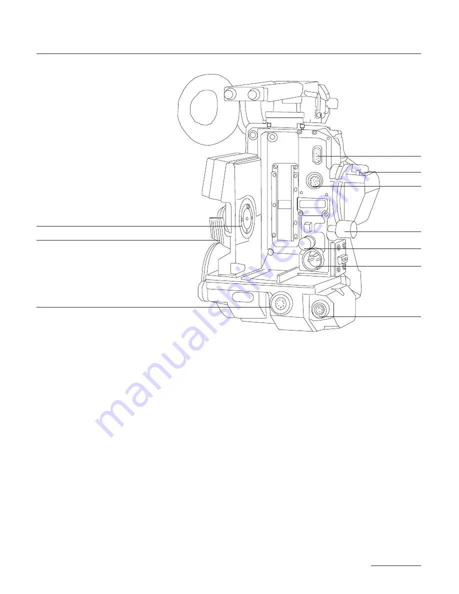
1.2 BACK VIEW

11

Magnetic Drive

provides magnetic magazine coupling.

12

Mag Release Lever

releases the magazine for removal.

13

Amph9

accessory input pr/-, Hz, and camera run functions.

14

Manual Iris Lever

controls CCD iris operation.

15

Lemo14

connects CCD head to the CCD control unit.

16

Battery Lock Screw

fastens the on-board battery to the camera body.

17

Camera Fuse

protects the body from excessive current and reverse polarity.

18

XLR4

main power input for on-board battery or other 12V power source.

19

Lemo8

accessory input pr/-, Hz, TVsync, 100PPF and camera run.

20

Lemo6

accessory input pr/- and camera run functions.

13

14

15

11

12

17

16

18

19

20

Summary of Contents for XTRprod

Page 1: ...X T R p r o d User s Guide September 2002 ...

Page 2: ...ation of the equipment described therein whether arising out of breach of warranty breach of contract or otherwise Under no circumstances shall Aaton or its li censors be liable for any damages arising out of the operation of the equipment described in this manual whether opera ted in a manner which is consistent with or contrary to the instructions contained therein for physical abuse or misuse o...

Page 3: ...djusting the Diopter 23 The Eyepiece Shutter 24 Adjusting the Viewing Horizon 24 Viewing Screen 24 Changing the Viewing Screen 25 Adujsting the Viewing Screen 26 Aatonite Illumination 27 2 3 Mirror Shutter 27 Concept 27 Adjusting the Shutter 28 2 4 Film Gate and Pulldown Claw 29 2 5 Flange Focal Distance Adjustment 29 Concept 29 Polishing a Spacer 30 Changing the Spacer 30 Adjusting the Viewing Sc...

Page 4: ...g the Control Panel 40 Aatonite 41 AatonCode 41 ASA Setting 41 Battery Voltage 42 Camera Preset Speed 42 Camera Specific Speed 42 Speed Phasing 42 Feet or Meters 43 Footage Remaining 43 Footage Elapsed 43 Mag ID 43 New Magazine s Footage 44 Camera Software Version Number 44 2 11 LED Indicators 44 Position and Meaning of the Diodes 44 Camera Test Indicator 45 Camera Run Indicator 45 Low Battery Ind...

Page 5: ...ate 61 The Claw Plate 61 3 4 Mag Identification System 62 Mag ID 62 Changing the ID of a Magazine 62 3 5 Loading 63 Feed Side In the Changing Bag 63 Take up Side In Daylight 63 3 6 The GX 800 ft mag 64 Feed side loading 64 Take up side loading 64 Mag ID 65 Footage 65 4 THE AATON SYSTEM 4 1 Camera Configurations 70 15mm Front Rods 70 Sliding Bridgeplate 70 4 2 Handgrip 71 Mounting the Handgrip 71 H...

Page 6: ...1 Lens 80 Lens Elements 80 Lens Exterior 80 Mounting Surface 80 5 2 Body 80 Exterior 80 Mounting Surfaces 80 Camera Gate 81 5 3 Viewing System 81 Viewing Screen 82 Eyepiece 82 Viewfinder 82 5 4 Magazine 83 Exterior 83 Pressure Plates 83 Interior Film Path 83 6 SUPER16 6 1 Super16 86 The Format 86 When to Shoot Super16 86 6 2 General Concerns 86 Protecting the Negative 86 Maintaining High Quality 8...

Page 7: ... AatonCode in the Camera 101 Using the OriginCplus Recommended Method 102 Using an External SMPTE Device 103 7 5 Monitoring and Maintaining AatonCode 103 Monitoring AatonCode with OriginCplus 104 Maintaining AatonCode without OriginCplus 104 7 6 GMT S 104 7 7 The Camera Assistant s Duties 105 Checking the Diodes 105 Setting the ASA 106 Checking for Running Time 106 8 TECHNICAL SPECIFICATIONS List ...

Page 8: ...8 ...

Page 9: ...SYSTEM FEATURES AND CONTROLS 9 1 ...

Page 10: ...rt which accesses the beamsplitter adjustment screw 5 CCD Cover accesses the CCD head 6 PL Lens Port standard mounting system for XTRprod XTRprod 7 Wooden Handgrip allows for comfortable handheld operation 8 Eyepiece Lock Ring fastens interchangeable standard and extension finders 9 Eyepiece Shutter blocks light when operator s eye is away from the finder 10 Body Run Test Switch provides camera ru...

Page 11: ...iris operation 15 Lemo14 connects CCD head to the CCD control unit 16 Battery Lock Screw fastens the on board battery to the camera body 17 Camera Fuse protects the body from excessive current and reverse polarity 18 XLR4 main power input for on board battery or other 12V power source 19 Lemo8 accessory input provides Hz TVsync 100PPF and camera run 20 Lemo6 accessory input provides and camera run...

Page 12: ...usts the diopter setting of the viewfinder to the operator s eye 25 Run Test Switch provides camera run and full frame inching from the handgrip 26 Take up Latch locks the magazine take up door 27 On board Battery 12V nicad for handheld operation 28 LED Indicators battery side indicators for camera run camera test and low battery 29 Lemo2 input provides camera run functions 30 Adjusting Screw adju...

Page 13: ...r display in the viewfinder 35 LED Indicators motor side indicators for camera run camera test and low battery 36 Motor triphase salarium low power consumption 3 75 fps operation 37 Aaton Jog provides quick adjustment of Aatonite ASA speed phasing footage 38 AatonCode Led flashes each second if the timecode has been initialized in the camera 39 Feed Latch locks the magazine feed door 40 Mag Footag...

Page 14: ...p 2 4 Adjusting a preset speed SET 1 x SYNC toggle SYNC or use Jog Sp 27 454 Adjusting a specific speed SET 1 x VAR use Jog Et Speed controled by external speed device SET 2 x VAR Phase Phase Adjusting Camera running SET 2 x VAR use Jog ISO 100 ASA Setting SET 1 x ISO toggle ISO or use Jog MAG 400 Indicating that the new magazine is fully loaded SET 2 x MAG MAG 140 Indicating the new magazine s fo...

Page 15: ...15 GENERAL OVERVIEW ...

Page 16: ......

Page 17: ...THE CAMERA BODY 17 2 ...

Page 18: ...cap is on re move it Align the four protruding flanges on the lens with the four corresponding cutaways in the locking ring and insert the lens into the camera port so that its flanges rest evenly against the lens seat Tighten the locking ring by turning clockwise until the lens is secu red in place and the lock ring is firmly set Make sure the lock ring 18 Flange focal distance Refers to the crit...

Page 19: ... left or right side viewing and an upright image in any position The viewfinder is equipped with a standard short eyepiece that can be used for handheld and tripod mounted operation For more comfortable tripod and studio applications the standard extension finder can be fitted in place of the short eyepiece With an Elemak or Mitchell type dolly or in situations requiring additional reach 19 THE CA...

Page 20: ...ill notice that the extension finder needs to face 180 away from the operator s eye to be installed onto the viewfinder Because of its optical construction this is completely normal After installation rotate the finder 180 to regular viewing position 2 2 3 Viewfinder Tension Adjustments The large knurled knob at the base of the left right lateral move ment point b locks the lateral positioning The...

Page 21: ...ots use this reference to quickly recall your particular setting when more than one person will be looking through the view finder The range of the diopter setting is or 3 If the range does not reach your particular diopter setting the viewfinder optics can quickly be adjusted by a qualified technician and the diopter range reset to meet your needs 2 2 5 The Eyepiece Shutter In order to avoid unwa...

Page 22: ...illiant screens which result from the use of this technology The XTRprod utilizes an interchangeable viewing screen system which allows the cinematographer to install the screen which best suits his particular application s Aaton offers ten viewing screens as standard see the Technical Specifications chapter Specially marked screens can also be manufactured to order Contact you local Aaton represe...

Page 23: ...ol until it is snug Carefully pull the screen straight out To reinstall the screen screw the Vw tool into the threaded hole of the screen until it is snug Look into the port and locate the left and right lip of the viewing screen holder With its flat side facing down gently push the screen straight into the holder above the lip until it seats firmly in place Unscrew the Vw tool and store back in t...

Page 24: ...erred to as Aatonite The level of illumination is adjustable by the user via the Jog wheel which is located to the right of the motor To operate Aatonite power the body and switch the run test switch to test posi tion and off again to turn on the camera electronics Look through the viewfinder and rotate the jog to set the desired level of illumina tion The markings will remain illuminated for a fu...

Page 25: ... HMI lighting without flicker 150 for filming at 25 fps under 60 Hz HMI lighting without flicker 144 for filming to minimize the roll bar while filming an NTSC broadcast monitor at 24 fps 2 3 2 Adjusting the Shutter To adjust the shutter opening unscrew the blue shutter tool marked Sh located in the hollow at the rear of the camera s carrying handle Make certain that the battery is off the camera ...

Page 26: ...en the adjustment is complete remove the tool and store back in the hollow of the carrying handle 2 4 FILM GATE AND PULLDOWN CLAW 2 4 1 Co planar Movement All Aaton cameras incorporate a patented means of advancing the film called a co planar claw movement By utilizing this technique Aaton is able to achieve an ultra precise pulldown with a minimal number of moving parts The co planar concept is t...

Page 27: ...area and an unuseable shot Aaton has taken steps in the design of their magazines and gate as sembly to ensure hair and dust free images The Aaton magazine features a twistless film path with little sprocket contact which mi nimizes the amount of film dust that builds up before entry into the aperture area 4 3 Cleaning the Gate In order to avoid film dust buildup in the recessed channels of the ga...

Page 28: ...ly 2 5 3 Changing the Spacer The spacer is placed between the lens port and the camera body s ti tanium lens holder If you re camera is equipped with a PL lens port you first need to remove the lens locking ring screw two or three turns its stop placed on the bottom inside the PL port and turn the ring counterclockwise Remove the lens port by unscrewing its screws Then remove the aluminium spacer ...

Page 29: ...nstant mag design allows for instantaneous switching between mags on the set To install the magazine on the camera situate your self towards the rear motor side of the camera body If the aperture cover plate is on remove it Place your left hand around the front of the camera just underneath the lens area Grasp the magazine firmly with your right hand below the midway point of its rear While hol di...

Page 30: ...l the magazine straight off the camera with your right hand 2 7 POWER XTRprod body requires only 12 volts for all aspects of operation One standard Aaton on board 12V 3 2 ah rechargeable Nimh will power the camera CCD and any accessories which are connected to the body s accessory inputs such as zoom controls speed controls etc through a standard 4 pin XLR connector One 3 2 ah on board battery wil...

Page 31: ...to the right of the motor or checking the control panel 2 7 2 Battery Charging The Aaton on board can be recharged with an appropriate 12V Nimh battery charger For the best results use a microprocessor controlled charger or a standard trickle charger with a charging output of at least 200ma both of which prevent the overheating and mistreatment of your Nimh cells Always follow the specific guideli...

Page 32: ... 24 25 29 97 30 36 40 48 60 and 75 fps The preset speed selector SYNC allows for quick access to these frequently used speeds If any other speed is desired or if the camera speed must match the frequency of a monitor to eliminate a roll bar the specific speed se lector EX VAR should be employed The specific speed selector enables the body to run at any speed between 3 and 75 in 001 fra me incremen...

Page 33: ... however will increa se mechanism wear increase noise and compromise image registra tion Aaton urges to avoid such usage at all cost and will not be res ponsible for the resulting damage that may occur This top speed cap of 75 fps has been designated by Aaton because it is the level at which the camera can run safely without any adverse effects on its mechanics 2 8 3 Electronic Inching The inching...

Page 34: ...third of a stop while normal exposure darkens the center green diode Underexposure of 2 stops or more darkens the green diode on the left end of the row overexposure of 2 stops or more darkens the green diode on the furthest right of the display To the immediate left of the display is the red diode indicator whi ch has the same functions as the red diodes on the left and right sides of the body Se...

Page 35: ...adjusting the sensi tivity reading of the lightmeter 1 Evenly light a standard 18 grey card 2 With a loaded magazine and lens on the camera frame the chart so that it completely fills the Super16 frame 3 With a properly calibrated handheld lightmeter take a reading of the grey surface and set the T stop of the lens accordingly 4 Switch the camera to run or test position and check the posi tion of ...

Page 36: ...sed it may be turned off The on off toggle switch is located on the operators side to the left of the mo tor Keep in mind the red diode indicator and end of film warnings will function whether the display is on or off 2 10 LCD CONTROL PANEL AND JOG 2 10 1 The Aaton Jog Located to the immediate right of the motor the Aaton jog is a small wheel designed to simplify many user functions When used in c...

Page 37: ...bility of recording AatonCode in camera time Timecode information is exposed onto the film by means of seven micro diodes which are re layed by means of fiber optics into the gate above the claw to the right of the aperture opening These micro diodes flash rapidly to form the code as the film rolls through the gate between exposures For more elaborate information regarding the uses and functioning...

Page 38: ...etween 25 and 1000 ISO by toggling Batt Iso or by rotating the jog wheel If the ISO selector is adjusted while the camera is in test or run po sition the correction will not take place until the next camera start 2 10 6 Battery Voltage Press button 3 to read the voltage of the camera s power source No tice that if the camera is running and button 3 is pressed the control panel will read and displa...

Page 39: ...nel can be set to count in either feet or meters in the following manner Unplug power from the camera until the display goes dark Simultaneously press button MAG while plugging power back in Continue to hold button MAG and set camera Run Test switch to test position foot or meter will show on the display Toggle button MAG to make your selection 2 10 11 Footage Remaining The control panel will disp...

Page 40: ... only a counter and it must be set by the user There is however a mecha nical footage counter on the magazine that automatically measures the size of the camera roll use the magazine footage counter to de termine the correct short end length to input on the control panel 2 10 15 Camera Software Version Number If you need to know the software version number your camera is equipped with proceed as f...

Page 41: ... Camera Run Indicator Yellow diode is on Red diode is off 2 11 4 Low Battery Indicator Yellow diode is on Red diode is flashing slowly The LCD control panel displays Lo Batt 2 11 5 Low Speed Indicator Yellow diode is on Red diode is blinking fast The LCD control panel displays Lo Speed Displaying a 5 Digit Speed If the XTRprod is set to a variable 5 digit speed the control panel will only display ...

Page 42: ...ery 4 seconds to indicates that 8 hours have now been elapsed since the timecode was initialized or controlled in the camera You need here to re initialize or to control you camera timecode 2 12 CCD ASSIST The Aaton VSA Video Synch Assist color CCD tap is designed to add video assist capability to the XTRprod without compromising the body s size flexibility and ease of use Because the CCD head is ...

Page 43: ...yepiece From body 1928 and on the beamsplitter delivered as standard from the factory has a 75 25 reflection ratio This means that 25 of the light from the viewfinder is sent to the CCD target when the beamsplitter is in place Although not visible from the outside of the body the 75 25 beamsplitter is identified by its blue anodized hol der Also available is a 50 50 beamsplitter which sends a grea...

Page 44: ...xis adjustment is used to recenter the CCD assist image when switching between 16 and Super16 formats If when you turn on the control unit the image on your monitor appears off to one side the angle of the beamsplitter must be adjusted The beamsplitter axis adjustment is located to the above right of the aperture and consists of an allen screw within a slot see diagram on the following page A red ...

Page 45: ...running from one 12V 3 2 ah on board battery For this reason it is recommen ded to use a battery block or AC power supply when using the VSA for long periods of time Although battery life will vary greatly depending on the amount of film run and the number of accessories powered from one power source you could estimate that one 12V on board could run 10 ma gazines and the VSA for 2 3 hours In orde...

Page 46: ...hnician Contact your Aaton re presentative for further details 1 Unscrew the four allen screws as indicated in the diagram be low and remove the PBX cover plate and rubber gasket On the co ver plate you ll notice a plastic plug which is press fit into the cover plate Remove this plug by pushing it to the inside of the plate If it is very tight use a pencil eraser to do the job On some cameras you ...

Page 47: ...into the tubular holder until the steel collar is stopped by the tube 4 While holding the head assembly in place locate the allen set screw in the diagram above and tighten moderately until the head assembly is secure To avoid any damage to the relay lens housing do not overtighten this screw 5 Position the Lemo14 in its cutout within the PBX and hold in place Make sure that the flat index towards...

Page 48: ...vie wing screen on the monitor If this is not the case the beamplitter may be retracted Remove the beamsplitter access cap on the battery side of the camera and position the beamsplitter by rotating the ad justment screw approximately 30 turns counter clockwise until it reaches its stop Back off the stop one turn clockwise 8 Locate two allen head screws on the CCD head identified by a red dot mark...

Page 49: ...D assist in two different ways In some special situations if you re filming in the dark for example it might be more comfortable to look your images on a monitor than through the viewfinder This is why the VSA is equipped with a frame generator as you can choose the size and position of the ge nerated frame the image you see through the viewfinder which might be in ratio 1 78 or 1 66 for example c...

Page 50: ...f I4 6KfI KO2 0M W Mg I X N 7 B1 e 7H h hI46Ke S M W2 6X g 7H hN1 3 C5 e h heI4 6T Y W2 6X W Mg I Xg he L V40Y J5 W5 h hf I H W M gI X 7H hN1g 3L hJ5 S X fW Y J H h V L 7Hh N1 he g V Kg O Y R Ke O Ye7Y h N1 he 3L hJ5hV4 0Y 3 LV4 0Y J5 h 3Lh J5 V Kg O Y N X gW HJ5 h V K gO Y V4 0Y Xf W 5 7H h V4 0Y V4 K eO 0Y h 3L I4 0MeJ5 h N1 he7H h 3Lhe h N1h J5 h W X h 7H eO X e W X h R Xe 3L hJ5 eN1e N1 h7H X ...

Page 51: ...o choose the top left position of the fra me Use arrows to proceed Frame Bottom Right allows you to choose the bottom right position of the frame Use arrows to proceed Frame move allows you to move the complete frame in the picture Use arrows to proceed Edge Shadow allows you to choose between a white or black edge around the frame or no edge Use arrows to proceed 51 THE CAMERA BODY Vitc lines Fir...

Page 52: ... an automatic shut off of the video assist from 10 to 60 minutes Use arrows to proceed Vitc Position allows you to choose the position of the Vitc lines Choose between line 10 and 19 in PAL Aaton recommends line 19 between 13 and 19 in NTSC Parity allows you to select the parity of the Vitc lines between Odd and Even Make sure that your Post production tools run properly with the se lected value L...

Page 53: ...53 THE CAMERA BODY ...

Page 54: ......

Page 55: ...THE MAGAZINE 55 3 ...

Page 56: ...rated 16mm film stock 400 feet of film is approximately 10 5 running minutes at 24 fps 3 2 COMPATIBILITY 3 2 1 DX Magazines Since the introduction of the XTR in 1984 only DX magazines ha ve been manufactured by Aaton all of which can be used on today s XTRprod approximate ser 3500 and above The DX code distin guishes this magazine from earlier designs D refers to its emulsion out Super16 safe coax...

Page 57: ...ded magazine is atta ched to the camera these pressure plates provide the precise stabilization of the film during exposure and transport 3 3 1 The Picture Plate The upper four striped pressure plate called the picture plate is po sitioned at the camera s aperture opening and is designed to hold the film steady at the point of exposure Proper setting and functio ning of the picture plate assures t...

Page 58: ...eceiver combination for each 3 4 2 Changing the ID of a Magazine The Mag ID of a particular magazine can be easily changed by the user Determine the magnetic receiver s that need to be changed ac cording to the chart above Locate the small silver spanner tool loca ted on the coaxial roller in the feed side of the mag Using this tool loosen and remove these receiver s A spare receiver is located at...

Page 59: ...b and forefinger to release core lock Place the film on the feed spindle with its wind clockwise and press the center of the core lock to lock the core in place Thread 4 of film around the outside of the lower guide roller and through large coaxial roller emulsion out Make sure that the length of film feeds completely through to the take up side Close and lock the feed door and engage the footage ...

Page 60: ...outside of the nose Pull through about one foot in length Reintroduce the film into the lower slot back into the magazine Place a plastic take up core onto the take up spindle check that the core is seated properly and press the center of the core lock to lock the core in place Bypass the lower sprocket for now and pass the film underneath the lower roller Fit the film end into a plastic take up c...

Page 61: ...ze can quickly be measured by in serting two fingers within the loop perpendicular to the mag s pressure plates At first determine proper loop size by pulling the looped film away from the mag counting and adjusting for 15 to 16 vi sible perforations for a length 14 to 15 frames long Then insert two fingers and check how the spacing relates to the proper loop length Of course each person s finger ...

Page 62: ...H J 5 e H 7 H h e J 5 7 H h e 7 N W 0 Y V 4 K h J e 7 X 7 H e J 5 e 5 h f 7 H h J 5 3 0 M I 6 X g 7 e V 5 J 5 f 7 H J H h f J 5 h 7 H V M V K f J J 5 H 7 H e J 7 h e J 5 7 H h N 0 Y V 4 6 K O 5 7 H J J 5 e 7 5 J 5 h e 7 H J 5 h e J 5 3 0 M I 4 0 Y J 5 7 5 7 H e H 7 H h e 7 H h e 7 H N I 4 M e 7 H J H J f J 5 e 5 h f J 5 h J 5 3 W 0 Y e J 5 7 5 7 5 f 7 H J H h f 7 H J 5 h 7 H V L O f 7 H J H H f 7 ...

Page 63: ...0 Y 1 V T L g 7 H f h e f O h O 0 M I 4 6 K I 4 W M e I 4 1 h f N h f W Y h W M J 5 L N Y 1 g f h e O 2 g W 2 0 M I 4 6 K I 4 Y g I Y L h f h f W Y h W Y 7 H J 1 e 3 W L g f h e f O 0 M I 4 6 K I 4 Y h V X h f 3 h f W Y h W Y e 5 7 5 3 L V Y 1 g h f J f J h J 0 M e 5 e W 2 0 M I 4 6 K I 4 H h e N 1 h f N 5 h f W Y h W Y e H J H N 1 N W L f h f 7 f 7 5 h 7 f J H e W 0 M I 4 6 K e 5 h f 3 L h e H h ...

Page 64: ......

Page 65: ...THE AATON SYSTEM 65 4 ...

Page 66: ...n Aaton manufactures 60mm and 120mm length rods that screw di rectly into the front housing of XTRprod underneath the lens port The 15mm front rod system is recommended when standard size lenses and accessories are to be used or when quick conversion bet ween tripod and handheld modes is necessary 4 1 2 Sliding Bridgeplate The XTRprod can also accept standard 15 and 19mm sliding brid geplates for ...

Page 67: ...sired location and fasten its center wing nut to secure the rods in position Attach the handgrip to the coupler by mating the star plate on the coupler to that on the hand grip adjusting to the desired position and fastening the T screw of the handgrip Connect the Lemo2 cable between the handgrip and camera body to add on off capability to the handgrip The Lemo2 connector is located on the battery...

Page 68: ...ed to the underside of the camera body with its standard 3 8 16 screw Make sure to use only a quick release plate screw provided by the manufacturer non standard screws longer than 8mm 1 3 can fracture the base casting and da mage the camera s electronics 4 4 SHOULDER OPERATION One of the most attractive features of the Aaton system has always been its comfort and ease of use in handheld situation...

Page 69: ...w longer than 10mm 7 16 longer screws can fracture the insert cas ting and damage the viewfinder s optics 4 5 2 Mounting from the Carrying Handle The 3 8 insert along with a guide hole at the rear of the handle can also be used to build a plate to undersling the camera or to configu re the rig for Steadicam low mode use For this reason the handle features a long flat top surface that is parallel t...

Page 70: ...areless mes senger services and airport handling When shipping and carrying your equipment it is always good practice to break down the package to its basic components whene ver possible Ship the body mags and batteries unattached and indi vidually padded Never under any circumstances ship the camera with a lens attached especially a zoom lens Shocks transferred from the outside of a case could ha...

Page 71: ...ch is designed to automatically turn on when needed and maintain the claw mechanism at a temperature of 15 F One of the cold hard facts of cold weather shooting is the conside rable reduction of battery life Do whatever possible to conserve your batteries and always carry more than usual Favor many small batteries such as on boards and lithium cells which are easier to keep warm over large block b...

Page 72: ...perature of the camera body down avoid having the camera exposed to direct sunlight for long periods of time by using a barney all weather cover or some form of shading like an umbrella Most importantly keep raw stock and magazines in a dry cooler or in the coolest location available 72 ...

Page 73: ...73 THE AATON SYSTEM ...

Page 74: ......

Page 75: ...CLEANING 75 5 ...

Page 76: ... with a Q tip lens tissue or cotton cloth 5 1 3 Mounting Surface Always inspect and keep the surfaces of your lens mounts clean using alcohol or a multi purpose cleaner with a Q tip Remember any debris found on the surface which contacts the lens seat can di rectly affect the back focus of your lens Make sure the Q tip does not leave any cotton fibers behind 5 2 BODY 5 2 1 Exterior Keep the extern...

Page 77: ...nder Use lens fluid applied with a cotton or preferably a foam Q tip for all areas By cleaning the viewing system in the order described below you will clean the more dust prone areas first which may help you track down most dirt particles sooner 5 3 1 Viewing Screen Look through the lens port at the reflection of the viewing screen in the mirror and check for visible dust particles Clear the mirr...

Page 78: ...is located on the inside of the eyepiece in the same fashion 78 Finding the dirt There is a simple means of locating much of the dirt within your viewing system Look through the viewfinder with no lens on the camera and adjust the diopter ring If the dust particles remain in focus they are most likely located on either side of the eyepiece If the dust comes in and out of focus as the ring is moved...

Page 79: ... necessary use De Solv It rubbed into the mag s surface with a cotton cloth Finish with alcohol applied with a cloth to restore its original finish 5 4 2 Pressure Plates The magazine pressure plates should be cleaned of dirt and film par ticles by means of a dust free cotton or chamois cloth After cleaning run your finger across their surface for a slight lubrication 5 4 3 Interior Film Path qOpen...

Page 80: ......

Page 81: ...SUPER16 81 6 ...

Page 82: ...o Shoot Super16 Generally speaking Super16 can be a good choice of origination in the following instances Any low budget theatrical production shot in 16mm for blow up to 35mm Any documentary or film that has the potential for future use in HDTV or some other widescreen aspect Any 16mm production that has a long shelf life or would like to extend the shelf life of their film by making it wide scre...

Page 83: ...imperfections which very often pass undetected on an NTSC or PAL screen are greatly magnified when viewed in a more demanding format The XTRprod with a registration tolerance of 1 2000 of the image dimension both laterally and horizontally delivers the most stable and exact imaging of any 16mm camera available Your Super16 images however will only be as sharp as the lenses you use to capture those...

Page 84: ...d camera reports that the exposed film is Super16 6 3 SHOOTING SUPER16 One of the most important aspects of shooting Super16 is achieving the full potential quality of the image The best way to maximize image quality is to reduce the amount of perceptible grain within the picture Factors such as film selection exposure and processing techniques will af fect the graininess of the resulting image 6 ...

Page 85: ...1 3 to one stop depending on the stock and the desired look When shooting Super16 for video transfer slight overexposure is re commended for the same reasons but care must be taken Overex posed negatives on a telecine require a higher gain which increases video noise The benefits of an overexposed negative however out weigh the additional noise introduced if the overexposure is kept wi thin one st...

Page 86: ...front unless otherwise noted 6 4 1 Before You Begin Before attempting a field conversion make sure you have the follo wing tools on hand 1 small slotted screwdriver 1 loupe approximately 5x magnification 1 standard metric Allen L wrench set sizes delivered with camera 1 orange stick 1 Port Alignment Tool part 09 100 62 for Aaton Port 09 100 61 for PL Port You ll also need the following equipment 1...

Page 87: ...its opening at a desk lamp or an overhead light source Situate the body so that the lens port is angled to face you Run the camera at normal speed the opening of the aperture plate should be easy to detect If this is not the case place a white piece of paper be hind the camera in your field of view With a loupe closely inspect the frame area If the light through the eyepiece is strong enough you s...

Page 88: ...shifted viewing screen Remove the viewfinder assembly from the camera by removing the four allen screws and spacer that hold the base of the viewfinder to the front housing Take note of the side on which the spacer has been removed The spacer is used to fill the gap that is created when shifting the viewfinder between formats Replace the viewfinder as sembly accordingly Secure the viewfinder by in...

Page 89: ...detailed in the diagram below Be sure not to damage the shims take extra care to align their cutouts around the holes to be used Fasten the screws then loosen each 1 2 a turn in preparation for fine centering 4 b Shifting the Aaton Lens Port Follow the procedure below if your camera is equipped with an Aa ton lens port If the port cap is on remove it Remove the lens stop knob by loose ning the sin...

Page 90: ...the screws of the lens port ring are loose enough that the ring can move independently of the lens holder Clear the mirror shutter as described in Step 1 so that it is rotated safely inside the body and the aperture opening could be seen from the lens port opening Make sure that the battery is removed from the body before proceeding further Remove the centering rod from the alignment jig and posit...

Page 91: ...lock stop knob screw hole is at the 2 o clock position Install the lock stop knob and secure its screw Install the port cap to check that the lens lock ring functions pro perly Method 2 via Lens Tracking Replace the lens lock ring and lock stop knob as described immedia tely above Check that the three allen screws of the lens port ring are just loose enough that the ring can move independently of ...

Page 92: ...o the viewing screen cross hair will track off in one direction Without moving the camera steady repo sition the lens and lens port ring until the target is centered Using an allen L wrench carefully tighten the screws enough to secure the lens port ring Set the zoom lens to telephoto position and check that the crosses remain centered If this is not the case reposition the body loosen the screws ...

Page 93: ...93 SUPER16 ...

Page 94: ......

Page 95: ...AATONCODE 95 7 ...

Page 96: ...nd recorder a slate is no longer needed for syncing purposes synchronization becomes fully automatic during the film tape trans fer or later post production stages An Aaton device called Keylink which consists of CCD reader heads and a PC and which is owned by the telecine house is desi gned to read Keycode and Aatoncode off the film during transfer and correlate this to the continuous video timec...

Page 97: ...ws a full minute for battery replacement before timeco de is lost 7 3 ORIGINCPLUS For the most efficient and foolproof means of working with Aaton Code it is highly recommended that an Aaton device called Ori ginCplus is used OriginCplus can be quickly programmed with a production ID full date and time of day then initialize timecode devices in either ASCII or SMPTE form Ori ginCplus is TCXO contr...

Page 98: ... and time of day Press the key to scroll through each field after all fields are set as desired Press to start the clock Make sure the camera has a battery attached Plug the Lemo5 cable of the OriginCplus into Lemo5 chassis mount on the base of the camera On the XTRprod the Lemo5 connector is located on the motor side to the lower left of the mo tor Press on the OriginCplus to send the timecode in...

Page 99: ...code device that will be supplying the ti mecode such as a Fostex PD2 or a Nagra IVS TC Set the time of day and date and set its clock to free run mode Connect a cable from the SMPTE output of the timecode device to the Lemo5 chassis mount on the base of the camera Set the on off switch on the camera to run or test position then off again this will send the timecode information to the camera bo dy...

Page 100: ...o monitor AatonCode drift OriginCplus will compare its own timecode to that of XTRprod OriginCplus will display Good fair bad or dif time different time followed by the amount of drift in tenths of a frame Follow the same procedure for each camera or sound recorder on the set running AatonCode When initializing or monitoring time code in a SMPTE device press 0 on the OriginCplus 7 5 2 Maintaining ...

Page 101: ... choose bet ween 24 25 29 97 and 30 fps To each choosen frequency corres pond one LED which flash every second You can also use the GMT1 as an OriginCplus supplier if one day by mistake you have forgotten to take your OriginCplus with you then use the GMT1 to initialize timecode in your camera The GMT1 with no timecode initialized inside is still able to generate a SMPTE code starting at 1h 00mn 0...

Page 102: ... the current ASA selection on the LCD control panel press the button marked ISO twice To adjust the ASA setting press SET then this button Make your selection between 25 and 1000 ISO by toggling the button or by rotating the jog wheel 7 7 3 Checking for Running Time The yellow LED located to the right of the motor will flash once per second on the second when timecode is running in the camera Get ...

Page 103: ...103 AATON CODE ...

Page 104: ......

Page 105: ...TECHNICAL SPECIFICATIONS 105 8 ...

Page 106: ...der and CCD target between formats Time recording AatonCode in camera at the gate matrix recording of man readable figures and machine readable data TCXO control for 1 2 fra me accuracy over 8 hours internal clock SMPTE and ASCII RS232 in Accessory inputs Amph9 video sync Lemo6 power zoom Lemo8 phase controllers Lemo14 CCD assist Lemo5 Smpte and RS232 time input and Lemo2 camera on off Video assis...

Page 107: ...ight 1 Batt motor 4 Batt 6 Start 2 3 5 Not used Lemo8 Speed Above and to 1 Batt Controllers the right of 2 TV Sync the left motor 3 ASCII In Out 4 Batt 5 100 PFF Out 6 Start 7 100 PFF In 8 Ground Amph9 Video Sync Above the 1 Batt left motor 2 TV Sync 3 2400 Hz 4 ASCII In Out 5 Batt 6 Batt 7 Strobe 8 Start 9 Batt XLR4 Power In Above the 1 Batt jog wheel 4 Batt 2 et 3 Not used pin socket Do not hook...

Page 108: ...108 AVAILABLE VIEWING SCREENS ...

Page 109: ...109 TECHNICAL SPECIFICATIONS ...

Reviews: