background image

2.8

Anti-tilt support

You may operate the max-e only with installed anti-tilt support.

If your wheelchair does not have a tilt support, which is standard with most
wheelchair manufacturers, we can equip your wheelchair with the necessary
anti tilt support as an optional accessory of the max-e.
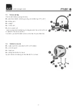
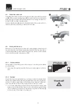
Holding devices

Œ

for our anti-tilt support are already mounted on the bra-

ckets of the max-e

2.8.1

Attaching and removing the tilt support

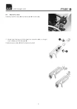
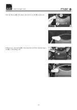
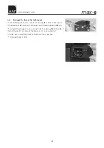
2.8.1.1 Universal holding device

Slide the tilt support



all the way into the holding device

Œ

on the max-e.

Lock it with the locking bolt

Ž

. Push the locking bolt into the drilling on the

holding device while you press the unlocking button



at the top of the lo-

cking bolt. When the locking bolt is inserted all the way you release the unlo-
cking button on the locking bolt.

F

Please check whether the locking bolts are tightly secured in the holding
devices. If you can remove the locking bolts without pressing the unlo-
cking button, they are not secured properly.

F

Please make sure that the tilt support is not jammed whenever you use
the max-e.

F

Please do not drive backwards against a wall with mounted tilt supports.

F

Please note that no tilt support can secure all potentially difficult situa-
tions, thus avoid any instable situations even with mounted tilt supports.

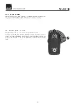
To remove the tilt support you press the unlocking button on the locking bolt
while you pull it out. Then take off the tilt support.

2.8.1.2 Multi holding device 1

Pull the locking bolt

Œ

out sidewise and slide the tilt support



all the way

into the holding

Ž

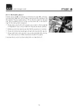
on the max-e. Please note the instructions written on the

tilt supports. The one marked with an "R" ist the tilt support for the right
side, the one marked with an "L" is the one for the left side, so that the dril-
lings for the locking bolts correspond.

F

Please make sure that the tilt supports are secured in their respective
holding devices. If you can pull them out, they are not secured properly.

F

Before you start driving make sure that the tilt supports are not jammed.

F

Please do not drive backwards against a wall with mounted tilt supports.

F

Please note that no tilt support can secure all potentially difficult situa-
tions, thus avoid any instable situations even with tilt supports.

To remove them you pull out the locking bolts and take them off.

15

max

-

e

Summary of Contents for max-e

Page 1: ...max e Operator s manual The power kit for your wheelchair...

Page 2: ...Alber Antriebstechnik GmbH was made at any one of the herein descri bed devices CE Signature of the manufacturer Markus Alber Managing associate AAT Alber Antriebstechnik GmbH The powered drive syste...

Page 3: ...ation of potential dangers 16 3 1 General information 16 3 2 Technical requirements 16 3 3 Operation 16 3 4 Environmental influences 17 3 5 Driving 17 3 6 Special tips for driving 17 4 Useful informat...

Page 4: ...ication class A according to EN 12184 Guidelines of the European Union In addition it also fulfills the require ments of application class B for indoor an outdoor use with one restriction The range li...

Page 5: ...l unit Connection to wheelchair Socket for the charging cable 1 1 4 Drive unit Drive Exit of the power line and socket for the charging cable Battery pack Connection to the wheelchair Control unit Ent...

Page 6: ...ries including straps 180 g charger 0 5 kg power cable 220 g Limits concerning the attachment to wheelchairs possible at a seat width of 28 cm Maximum total weight admitted 200 kg person wheelchair ma...

Page 7: ...well as a power cable battery bag holding device for the control unit and an operator s manual no picture In addition you need brackets which must be fixed to your wheelchair 1 4 Optional accessories...

Page 8: ...re specially developed and adjusted to each particular type of wheelchair The brackets in this picture right and left may look different from the ones on your wheelchair F Please make sure that the br...

Page 9: ...arefully insert the max e into the bracket on both sides F Please insert the max e with its wheelchair connections in a straight line in reference to the brackets The device easily slides into the bra...

Page 10: ...Now put the plug of the power cable into its socket on the max e Afterwards you put the plug of the power cable into the corresponding so cket on the battery pack 10 max e...

Page 11: ...ully At this point the wheel chair cannot be pushed manually any more 2 5 1 Starter protection Please make sure that the joystick of the max e is in neutral position before you start driving F start u...

Page 12: ...e be a radio failure the control system will try to use a different frequency to communicate with the drive This search may take several se conds During this time you cannot drive with the max e The j...

Page 13: ...ctions correctly 2 6 Adjustment of the hand reste The hand rest of the control unit can be adjusted to the user Loosen the screws on the bottom side of the control unit The hand rest is already equipp...

Page 14: ...2 7 Swivel arm The swivel arm is an optional accessory which makes it possible to swivel your control unit into several different positions 14 max e...

Page 15: ...u use the max e F Please do not drive backwards against a wall with mounted tilt supports F Please note that no tilt support can secure all potentially difficult situa tions thus avoid any instable si...

Page 16: ...the locking bolts correspond F Please make sure that the tilt supports are secured in their respective holding devices If you can pull them out they are not secured properly F Before you start driving...

Page 17: ...f the whelchair driver s weight the wheelchair and the max e F Please always check the air pressure of pneumatic steering rollers The max e s driving qualities could be affected negatively if there is...

Page 18: ...ted by the wheelchair manufacturer must be closely observed F Always start with the lowest possible speed Although max e masters gradients up to 20 you may never exceed the ad mitted gradient stipulat...

Page 19: ...he gripping rings on the wheels while braking You can bring about an immediate standstill by briefly pressing the joystick in the opposite di rection that you are driving F To keep the wheelchair from...

Page 20: ...rom its holding device when already turned on the joystick loses all functions At this point you cannot drive with the max e This is a precaution so that nobody except for the person sit ting in the w...

Page 21: ...te of the battery pack and the control unit as well as the le vel of speed Should the display for the battery charge or for the control unit reach the lo west bar the command charge batteries or charg...

Page 22: ...ing the charging cycle After the charging cycle is completed the control unit turns itself off auto matically after 5 minutes Overload If the max e does not remain within the diagram concerning weight...

Page 23: ...Malfunction A summary of all indications of malfunction you find in chapter 7 2 Potenti al malfunction 23 max e Error Drive Pressure not reached Acknowledge with...

Page 24: ...takes several charging discharging cycles before their full capacity emerges This applies to both the battery pack and the control unit The batteries may be charged in any kind of position They are co...

Page 25: ...lchair manually 6 1 3 Charge the battery pack and the control unit together You should charge the battery pack and the control unit together F Should you not use the control unit and the battery pack...

Page 26: ...each If the lower fuse is burnt out echange it with the extra upper fuse aus If you need to exchange a fuse put a pen into the opening on the side of the battery pack This unlocks the drawer so it ca...

Page 27: ...em turning on the max e please contact your dealer Batteries don t charge Please contact your dealer Power shafts do not emerge on one or both sides Loosen set screw of the horizontal adjustment locat...

Page 28: ...sure could not be reached Software control Error in the software of the control processor Malfunction of the drive unit Communication processors Explanation Under voltage Batteries in the drive unit a...

Page 29: ...lem you might have please first turn off the control unit If the power shafts do not run in automatically press the yellow emergency unlocking key on the side of the drive unit The power shafts drive...

Page 30: ...Make sure that water does not get into the max e F For security reasons please do not use a high pressure cleaning device 8 2 Maintenance The max e is a low maintenance device To ensure the functionin...

Page 31: ...ions done or additions made on the max e 9 2 Liability The manufacturer AAT Alber Antriebstechnik GmbH is not responsible for the safety of the max e if the max e was handled inappropriately the max e...

Page 32: ...max e AAT Alber Antriebstechnik GmbH Postfach 10 05 60 D 72426 Albstadt Tel 49 74 31 12 95 0 Fax 49 74 31 12 95 35 www aat online de info aat online de...

Reviews: