AAON SA-028 Installation Operation & Maintenance Download Page 16


16 

General Information 

 
SA Series self contained units and indoor air 
handling  units  have  been  designed  for 
indoor installation only. SA Series units can 
contain 

spring 

isolated 

direct 

drive 

backward  curved  plenum  fans,  shell  and 
tube 

or 

brazed 

plate 

water-cooled 

condensers,  R-410A  scroll  compressors, 
evaporator coils, chilled water cooling coils, 
steam  or  hot  water  heating  coils,  waterside 
economizers,  and  a  single  point  power 
connection.  Units  are  assembled,  wired, 
charged  and  run-tested  at  the  factory.  SA 
Series  units  are  not  intended  for  residential 
use. 


Codes and Ordinances 

SA  Series  units  have  been  tested  and 
certified,  by  ETL,  in  accordance  with  UL 
Safety Standard 1995/CSA C22.2 No. 236. 
 
System  should  be  sized  in  accordance  with 
the 

American 

Society 

of 

Heating, 

Refrigeration 

and 

Air 

Conditioning 

Engineers Handbook. 
 
Installation  of  units  must  conform  to  the 
ICC 

standards 

of 

the 

International 

Mechanical Code, the International Building 
Code,  Installation  of  Air  Conditioning  and 
Ventilating  Systems  Standard,  NFPA  90A, 
and  local  building,  plumbing  and  waste 
water  codes.  All  appliances  must  be 

electrically  grounded  in  accordance  with 
local codes, or in the absence of local codes, 
the 

current 

National 

Electric 

Code, 

ANSI/NFPA  70  or  the  current  Canadian 
Electrical Code CSA C22.1. 
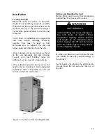


Receiving Unit 

When  received,  the  unit  should  be  checked 
for  damage  that  might  have  occurred  in 
transit. If damage is found it should be noted 
on  the  carrier’s  Freight  Bill.  A  request  for 
inspection by carrier’s agent should be made 
in writing at once.  
 
Nameplate  should  be  checked  to  ensure  the 
correct  model  sizes  and  voltages  have  been 
received to match the job requirements. 
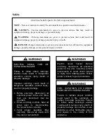


Improper 

installation, 

adjustment, 

alteration,  service  or  maintenance 
can 

cause 

property 

damage, 

personal injury or loss of  life. Startup 
and  service  must  be  performed  by  a 
Factory  Trained  Service  Technician. 
A  copy  of  this  IOM  should  be  kept 
with the unit. 


WARNING


The  Clean  Air  Act  of  1990  bans  the 
intentional venting of refrigerant as of 
July  1,  1992.  Approved  methods  of 
recovery,  recycling,  or  reclaiming 
must be followed. 


CAUTION 


Coils  and  sheet  metal  surfaces 
present  sharp  edges  and  care  must 
be 

taken 

when 

working 

with 

equipment. 


WARNING


Failure  to  observe  the  following 
instructions  will  result  in  premature 
failure  of  your  system  and  possible 
voiding of the warranty. 


WARNING


Summary of Contents for SA-028

Page 1: ...loss of life FOR YOUR SAFETY Do not store or use gasoline or other flammable vapors and liquids in the vicinity of this or any other appliance WARNING WARNING QUALIFIED INSTALLER Improper installation...

Page 2: ......

Page 3: ...Heat Exchanger Cleaning 33 Electrical 33 Cutting Electrical Openings 34 Thermostat Control Wiring 35 Duct Connection 36 Condensate Drain Piping 36 Waterside Economizer 37 Hot Water Coil 41 Chilled Wat...

Page 4: ...wnout Protection Module 51 Filter Replacement 53 Replacement Parts 54 AAON Warranty Service and Parts Department 54 Appendix A Heat Exchanger Corrosion Resistance 55 SA Series Startup Form 57 Maintena...

Page 5: ...ails 22 Figure 5 One Piece Dual Unit Lifting Details 23 Figure 6 Two Piece Dual Unit Coil Section Lifting Details 24 Figure 7 Two Piece Dual Unit Fan Section Lifting Details 25 Figure 8 Dual unit with...

Page 6: ...uld result in dangerous operation serious injury death or property damage Before servicing disconnect all electrical power to the unit More than one disconnect may be provided When servicing controls...

Page 7: ...ng an Arc Flash Boundary to be field established and marked for identification of where appropriate Personal Protective Equipment PPE be worn should be followed WARNING UNIT HANDLING To prevent injury...

Page 8: ...gen acetylene or air in place of refrigerant and dry nitrogen for leak testing A violent explosion may result causing injury or death WARNING Always use a pressure regulator valves and gauges to contr...

Page 9: ...ooled condenser See Appendix A Heat Exchanger Corrosion Resistance for more information CAUTION OPEN LOOP APPLICATIONS Failure of the condenser as a result of chemical corrosion is excluded from cover...

Page 10: ...unique to the model you have purchased 4 READ THE ENTIRE INSTALLATION OPERATION AND MAINTENANCE MANUAL OTHER IMPORTANT SAFETY PRECAUTIONS ARE PROVIDED THROUGHOUT THIS MANUAL 5 Keep this manual and all...

Page 11: ...on Protection F Option C Interior Corrosion Protection A1 Refrigerant Style 0 Air Handling Unit B R 410A Non Compressorized DX AHU E R 410A Variable Capacity Scroll Compressor A2 Unit Configuration 0...

Page 12: ...nomizer 6 Row Coil 1B Plenum Height 0 33 Plenum Height A 37 Plenum Height B 41 Plenum Height C 45 Plenum Height D 49 Plenum Height E 53 Plenum Height F 57 Plenum Height G 37 Plenum Height Sound Attenu...

Page 13: ...ved Plenum 5C Supply Air Blower Motor C 1 hp 1760 rpm D 2 hp 1760 rpm E 3 hp 1760 rpm F 5 hp 1760 rpm G 7 5 hp 1760 rpm H 10 hp 1760 rpm N 1 hp 1170 rpm P 2 hp 1170 rpm Q 3 hp 1170 rpm R 5 hp 1170 rpm...

Page 14: ...hers 5 Field Installed DDC Controls by Others with Isolation Relays 6 Factory Installed DDC Controls Furnished by Others with Isolation Relays 14A Water Cooled Condenser 0 Standard None A Balancing Va...

Page 15: ...ld Adjustable for Glycol 16 Interior Cabinet Options 0 Standard A Overflow Switch B UV Lights C Options A B 17 Blank 0 Standard 18 Blank 0 Standard 19 Code Options 0 Standard ETL U S A Listing D Chica...

Page 16: ...odes All appliances must be electrically grounded in accordance with local codes or in the absence of local codes the current National Electric Code ANSI NFPA 70 or the current Canadian Electrical Cod...

Page 17: ...at system switch to OFF or turn the unit off at the control panel and leave the unit off until the main power switch has been turned on again for at least 24 hours for units with compressor crankcase...

Page 18: ...of condensate lines Waterside economizer coil units include a separate condensate drain pan which drains into the evaporator coil drain pan No additional drain line is needed for the waterside economi...

Page 19: ...clearance requirements Allow adequate space for piping access and panel removal Condenser water piping and condensate drain connections are near the bottom on the back of the unit Figure 1 SA Series...

Page 20: ...20 Figure 2 One Piece Single Unit Lifting Details...

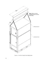
Page 21: ...21 Figure 3 Two Piece Single Unit Coil Section Lifting Details...

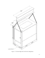
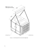
Page 22: ...22 Figure 4 Two Piece Single Unit Fan Section Lifting Details...

Page 23: ...23 Figure 5 One Piece Dual Unit Lifting Details...

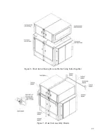
Page 24: ...24 Figure 6 Two Piece Dual Unit Coil Section Lifting Details...

Page 25: ...25 Figure 7 Two Piece Dual Unit Fan Section Lifting Details...

Page 26: ...plete unit A crow bar or similar tool can be used to line up the sections Factory provided bolts can then be used to secure the coil sections together See Figure 9 4 Align and set each fan section on...

Page 27: ...27 Figure 8 Dual unit without splices and before being bolted together Figure 9 Dual Unit Assembly Details...

Page 28: ...28 Figure 10 Dual unit with splices after being bolted together...

Page 29: ...s Any damage to the equipment as a result of condenser failure from chemical corrosion due the fluid in the condenser is excluded from coverage under AAON warranties and the heat exchanger manufacture...

Page 30: ...l solution is recommended Table 2 Glycol Freezing Points Glycol Ethylene Glycol Propylene Glycol 20 18 F 19 F 30 7 F 9 F 40 7 F 6 F 50 28 F 27 F Water loop piping runs through unheated areas or outsid...

Page 31: ...ust be controlled All make up water has minerals in it and as the water is evaporated in the cooling tower these minerals remain As the mineral content of the water increases the conductivity of the w...

Page 32: ...GPM PSI 45 4 2 45 4 2 45 4 2 45 1 7 39 3 3 39 3 3 39 3 3 39 35 2 8 35 2 8 35 2 8 35 SA 045 SA 050 SA 055 SA 058 GPM PSI GPM PSI GPM PSI GPM PSI 45 4 2 45 4 2 45 4 2 45 4 2 39 3 3 39 3 3 39 3 3 39 3 3...

Page 33: ...t of unit specific wiring diagrams showing factory and field wiring are laminated in plastic and located inside the controls compartment door All units require field supplied electrical overcurrent an...

Page 34: ...e that the metal skins of the foam part do not separate from the foam this would result in reduced structural integrity of the part Size supply conductors based on the unit Minimum Current Ampacity MC...

Page 35: ...determine the allowable wiring distances Table 5 Control Wiring Wire Size Stranded Copper Conductors Only Total Wire Distance Allowable 20 AWG 200 ft 18 AWG 350 ft 16 AWG 500 ft 14 AWG 750 ft 12 AWG 1...

Page 36: ...may be equipped with more than one condensate drain pan connection A p trap and drain line must be installed on every drain connection with the p trap not to exceed 6 from the drain connection The lin...

Page 37: ...hanical cooling only During waterside economizer only mode of operation condenser water flows through the waterside economizer coil with modulating valves maintaining supply air temperature setpoint T...

Page 38: ...s of factory provided piping assemblies Connect the piping assembly to the unit Connect the actuators to the water valves Actuators are factory wired and included inside the unit Installing contractor...

Page 39: ...ight Intake Piping Kit Left Intake Piping Kit Assembly 6 Assembly 1 Assembly 2 Assembly 3 Assembly 4 Assembly 5 Waterside Economizer Valve Waterside Economizer Bypass Valve Head Pressure Control Valve...

Page 40: ...zer Back View Right Intake Piping Kit Left Intake Piping Kit Assembly 6 Assembly 1 Assembly 2 Assembly 3 Assembly 4 Assembly 5 Waterside Economizer Valve Waterside Economizer Bypass Valve Head Pressur...

Page 41: ...ks on the performance of the unit This includes checking of the air flow the air filters condenser water flow and refrigerant charge Supply Fans SA Series units are equipped with direct drive backward...

Page 42: ...bolt and rotate the locking nut counter clockwise approximately four full rotations This will allow the locking nut to spin when the adjustment bolt is turned See Figure 17 Turn adjustment bolt count...

Page 43: ...wheels or with VFDs Field airflow adjustment may be required at startup Air volume bands for the wheels are sized according to the unit s air delivery specifications and can also be ordered from the...

Page 44: ...nd equipped with easy bend tabs that are to be inserted into pre punched slots provided on the wheel Once the band has been inserted into the slots it MUST BE secured by bending the tabs over from the...

Page 45: ...proper charge After charging unit should be operated in cooling mode to check for correct charge Charge may need to be adjusted for cooling mode If adjustments are made in the cooling mode heating mod...

Page 46: ...ser Air Source Heat Pump Sub Cooling 12 18 F Sub Cooling with Hot Gas Reheat 15 22 F Superheat 8 15 F Water Cooled Condenser Water Source Heat Pump Sub Cooling 4 8 F Sub Cooling with Hot Gas Reheat 4...

Page 47: ...87 261 4 114 384 6 141 547 0 34 105 0 61 172 5 88 265 4 115 389 9 142 553 9 35 107 1 62 175 4 89 269 4 116 395 2 143 560 9 36 109 2 63 178 4 90 273 5 117 400 5 144 567 9 37 111 4 64 181 5 91 277 6 11...

Page 48: ...charge See Startup section for information on air flow adjustment and refrigerant charge adjustment DX Cooling Set unit controls to cooling mode of operation with supply fans on Check the fans for cor...

Page 49: ...an e coated coil and is required to maintain coating warranty coverage Coil cleaning shall be part of the unit s regularly scheduled maintenance procedures Failure to clean an e coated coil will void...

Page 50: ...ended that a hose be used as a pressure washer will damage the fins The water to be used for the rinse is recommended to be of potable quality though a lesser quality of water may be used if a small a...

Page 51: ...the restart time delay All settings and the last 4 faults are retained even if there is a complete loss of power DPM Setup Procedure With the supply voltage active to the module you can setup all of t...

Page 52: ...Screen Vertical Format Default 2 sec Manual 2S 3S 4S 5S 6S 7S 8S 9S 10S 30S 1M 2M 3M 4M Phase Imbalance Percentage Screen Vertical Format Default 5 3 4 5 6 7 8 9 10 Fault Screen Vertical Format 0 most...

Page 53: ...Table 11 45 70 tons Pre Filters Feature 6A Quantity Size Type 0 No Pre Filters A 18 20 x 20 x 2 Pleated 30 Eff MERV 8 Table 12 23 35 tons Unit Filters Feature 6B Quantity Size Type 0 9 20 x 20 x 2 Ple...

Page 54: ...number and part number when ordering parts AAON Warranty Service and Parts Department 2424 S Yukon Ave Tulsa OK 74107 Ph 918 382 6400 Fax 918 382 6364 www aaon com Note Before calling technician shoul...

Page 55: ...orrosion problems may occur especially when more factors are valued 0 Use is not recommended Water Containing Concentration mg l or ppm Time Limits Analyze Before AISI 316 SMO 254 Copper Alloy Nickel...

Page 56: ...t 0 2 0 Manganese Mn 0 1 No Limit 0 1 0 Chloride Content Chloride Content Maximum Temperature 60 C 140 F 80 C 176 F 120 C 248 F 130 C 266 F 10 ppm SS 304 SS 304 SS 304 SS 316 25 ppm SS 304 SS 304 SS 3...

Page 57: ...es No 2 Is the unit level Yes No 3 Are the unit clearances adequate for service and operation Yes No 4 Do all access doors open freely and are the handles operational Yes No 5 Have all shipping braces...

Page 58: ...sure PSIG Suction Pressure PSIG 1 2 3 4 Refrigeration System 1 Cooling Mode Pressure Saturated Temperature Line Temperature Sub cooling Superheat Discharge N A N A Suction N A Liquid N A Refrigeration...

Page 59: ...A Liquid N A Refrigeration System 2 Heating Mode Heat Pump Only Pressure Saturated Temperature Line Temperature Sub cooling Superheat Discharge N A N A Suction N A Liquid N A Refrigeration System 3 He...

Page 60: ...o 2 Has the entire system been filled with fluid Yes No 3 Has air been bled from the heat exchangers and piping Yes No 4 Is the glycol the proper type and concentration N A if water Yes No 5 Is there...

Page 61: ...cument any service repair or adjustments AAON Service and Warranty Departments are available to advise and provide phone help for proper operation and replacement parts The responsibility for proper s...

Page 62: ...adding the brazed plate heat exchanger cleaning instructions November 2012 Update of the IOM adding information about compressor cycling July 2013 Updated qualified installed warning and removed warr...

Page 63: ...63...

Page 64: ...Technical Support 918 382 6400 Note Before calling Technical Support please have the model and serial number of the unit available Parts For replacement parts please contact your local AAON Representa...

Reviews: