background image

E P I C   B o a r d    

E P I C - B D U 7


Chapter 2 Quick Installation Guide

 2-4


With Heat Spreader 


Summary of Contents for EPIC-BDU7

Page 1: ...Board E P I C B D U 7 EPIC BDU7 Intel Core i3 i5 i7 ULT Processor SoC DDR3L 1600 SODIMM 2 Mini PCIe Socket 4 USB 2 0 2 USB 3 0 6 COM 2 SATA 1 mSATA VGA LVDS DP EPIC BDU7 Rev A Manual 2 nd Ed August 27...

Page 2: ...reproduced copied translated or transmitted in any form or by any means without the prior written permission of the original manufacturer Information provided in this manual is intended to be accurat...

Page 3: ...is trademark of Advanced Micro Devices Microsoft Windows is a registered trademark of Microsoft Corp ITE is a trademark of Integrated Technology Express Inc IBM PC AT PS 2 and VGA are trademarks of I...

Page 4: ...installing your card please make sure that the following materials have been shipped DVD ROM for manual in PDF format and drivers EPIC BDU7 If any of these items are missing or damaged please contact...

Page 5: ...EPIC Board E P I C B D U 7 China RoHS Requirements AAEON Main Board Daughter Board Backplane Pb Hg Cd Cr VI PBB PBDE O SJ T 11363 2006 X SJ T 11363 2006 iv...

Page 6: ...s PBDE PCB Other Components X O O O O O Wires Connectors for External Connections X O O O O O O The quantity of poisonous or hazardous substances or elements found in each of the component s parts is...

Page 7: ...st of Connectors 2 7 2 6 Setting Jumpers 2 9 2 7 PCI 104 I O Voltage Selection JP1 2 10 2 8 Clear CMOS Jumper JP2 2 10 2 9 Touchscreen 4 5 8 Wire Mode Selection JP3 2 10 2 10 AT ATX Power Supply Mode...

Page 8: ...12V CN3 2 13 2 22 Main Power Input 9V to 24V CN4 2 14 2 23 PCI 104 Connector CN5 2 14 2 24 High Definition Audio CN6 2 16 2 25 USB 2 0 Port 4 CN7 2 17 2 26 Front Panel CN8 2 17 2 27 LPT Digital IO Por...

Page 9: ...9 2 46 COM Port 3 RS 232 422 485 CN29 2 39 2 47 USB 2 0 3 0 Port 1 2 CN30 2 42 2 48 Display Port 2 CN31 2 43 2 49 LVDS Port 2 CN32 2 44 2 50 COM Port 1 2 CN33 2 46 2 51 VGA Port CN34 2 48 2 52 Display...

Page 10: ...y Address Map B 4 B 3 IRQ Mapping Chart B 5 B 4 DMA Channel Assignments B 17 Appendix C Mating Connector C 1 List of Mating Connectors and Cables C 2 Appendix D Electrical Specifications for I O Ports...

Page 11: ...EPIC Board E P I C B D U 7 General Information Chapter 1 Chapter 1 General Information 1 1...

Page 12: ...ort for 4K resolution videos as well as independent displays With low power consumption and compactness being the key aspects in 21 st century computer designs the board runs on 15WDP while providing...

Page 13: ...1600 SODIMM up to 8GB VGA LVDS1 DP LVDS2 Optional eDP Optional Intel WGI211AT WGI218LM x 1 RJ 45 x 2 SATA 3 6 0Gb s x 2 mSATA x 1 USB 2 0 x 4 USB 3 0 x 2 RS 232 x 4 RS 242 422 485 x 2 Touch panel cont...

Page 14: ...essor SoC Ethernet Intel WGI211AT x 1 WGI218LM x 1 BIOS AMI BIOS Wake On LAN Yes Watchdog Timer 1 255 sec support by AAEON Hi Safe H W Status Monitoring Supported by AAEON Hi Safe Expansion Interface...

Page 15: ...F 140 F Storage Temperature 40 C 80 C 40 F 176 F Operation Humidity 0 90 Relative Humidity Non Condensing Display Chipset 5 th Generation Intel Core i3 i5 i7 ULT Processor SoC Resolution CRT up to 192...

Page 16: ...4 RS 232 422 485 x 2 Ring 5V 12V Parallel Port SPP EPP ECP x 1 Optional controlled by BIOS DI O 16 bit digital I O interface co lay with LPT Port controlled by BIOS DI O default Audio Realtek ALC 892...

Page 17: ...EPIC Board E P I C B D U 7 Chapter 2 Quick Installation Guide 2 1 Quick Installation Guide Chapter 2...

Page 18: ...le the power is on because a sudden rush of power can damage sensitive electronic components Always ground yourself to remove any static charge before touching the board Modern electronic devices are...

Page 19: ...EPIC Board E P I C B D U 7 Chapter 2 Quick Installation Guide 2 3 2 2 Dimensions Component Side Component Side Component Side...

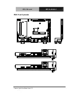
Page 20: ...EPIC Board E P I C B D U 7 Chapter 2 Quick Installation Guide 2 4 With Heat Spreader...

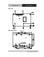
Page 21: ...EPIC Board E P I C B D U 7 Chapter 2 Quick Installation Guide 2 5 Solder Side Solder Side With Heat Spreader...

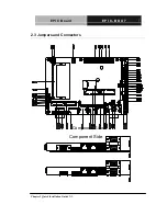
Page 22: ...EPIC Board E P I C B D U 7 Chapter 2 Quick Installation Guide 2 6 2 3 Jumpers and Connectors Component Side Component Side...

Page 23: ...2 Clear CMOS Jumper JP3 Touch Screen 4 5 8 Wire Mode Selection JP4 AT ATX Power Supply Mode Selection JP10 LVDS Port1 eDP Backlight Inverter Voltage Selection JP11 LVDS Port1 eDP Operating Voltage Sel...

Page 24: ...reo Audio RIGHT Channel CN2 Stereo Audio LEFT Channel CN3 Main Power Input 12V ONLY CN4 Main Power Input 9V to 24V CN5 PCI 104 Connector CN6 High Definition Audio CN7 USB 2 0 Port 4 CN8 Front Panel CN...

Page 25: ...M 100M 1G Ethernet Port 1 CN27 10M 100M 1G Ethernet Port 2 CN28 COM Port 4 RS232 CN29 COM Port 3 RS232 485 422 CN30 USB 2 0 3 0 Port 1 2 CN31 Display Port 2 CN32 LVDS Port 2 CN33A COM Port 1 RS232 CN3...

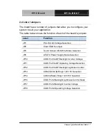
Page 26: ...hem To close a jumper you connect the pins with the clip To open a jumper you remove the clip Sometimes a jumper will have three pins labeled 1 2 and 3 In this case you would connect either pins 1 and...

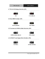
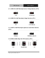
Page 27: ...tage Selection JP1 1 2 3 5V 1 2 3 3 3V Default 2 8 Clear CMOS Jumper JP2 1 2 3 Normal Default 1 2 3 Clear CMOS 2 9 Touchscreen 4 5 8 Wire Mode Selection JP3 1 2 3 4 8 Wires Mode Default 1 2 3 5 Wires...

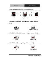
Page 28: ...3 VR Mode 1 2 3 PWM Mode Default 2 14 COM2 D SUB Ring 12V 5V Selection JP13 1 2 3 4 5 6 1 2 3 4 5 6 1 2 3 4 5 6 1 2 3 4 5 6 1 2 3 4 5 6 1 2 3 4 5 6 1 2 3 4 5 6 1 2 3 4 5 6 1 2 3 4 5 6 1 2 3 4 5 6 1 2...

Page 29: ...6 1 2 3 4 5 6 1 2 3 4 5 6 1 2 3 4 5 6 1 2 3 4 5 6 1 3 5 1 2 3 4 5 6 1 2 3 4 5 6 1 2 3 4 5 6 Ring Default 1 2 3 4 5 6 1 2 3 4 5 6 1 2 3 4 5 6 1 2 3 4 5 6 1 2 3 4 5 6 1 2 3 4 5 6 1 2 3 4 5 6 1 2 3 4 5...

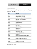
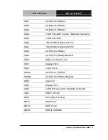
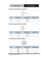
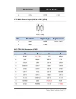
Page 30: ...ereo Audio Right Channel CN1 Pin Pin Name Signal Type Signal Level 1 R OUT 2 R OUT 2 20 Stereo Audio Left Channel CN2 Pin Pin Name Signal Type Signal Level 1 L OUT 2 L OUT 2 21 Main Power Input 12V CN...

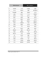
Page 31: ...4 Pin Pin Name Signal Type Signal Level 1 VIN PWR 9V to 24V 2 GND GND 2 23 PCI 104 Connector CN5 A B C D 1 GND 5V_SB 5V AD00 2 VI O AD02 AD01 5V 3 AD05 GND AD04 AD03 4 C BE0 AD07 GND AD06 5 GND AD09 A...

Page 32: ...BE2 15 AD18 3 3V AD17 GND 16 AD21 AD20 GND AD19 17 3 3V AD23 AD22 3 3V 18 IDSEL0 GND IDSEL1 IDSEL2 19 AD24 C BE3 VI O IDSEL3 20 GND AD26 AD25 GND 21 AD29 5V AD28 AD27 22 5V AD30 GND AD31 23 REQ0 GND...

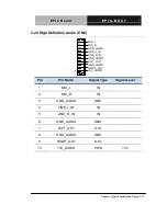
Page 33: ...dio CN6 MIC_L 1 10 MIC_R LINE_L_IN LINE_R_IN LEFT_OUT RIGHT_OUT 5V_AUDIO GND_AUDIO GND_AUDIO GND_AUDIO Pin Pin Name Signal Type Signal Level 1 MIC_L IN 2 MIC_R IN 3 GND_AUDIO GND 4 LINE_L_IN IN 5 LINE...

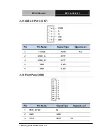
Page 34: ...Installation Guide 2 18 2 25 USB 2 0 Port 4 CN7 Pin Pin Name Signal Type Signal Level 1 5VSB PWR 5V 2 USB3_D DIFF 3 USB3_D DIFF 4 GND GND 5 GND GND 2 26 Front Panel CN8 Pin Pin Name Signal Type Signal...

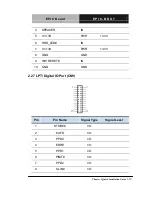
Page 35: ...de 2 19 4 SPEAKER IN 5 V3 3S PWR 3 3V 6 HDD_LED IN 7 V3 3S PWR 3 3V 8 GND GND 9 H W RESET IN 10 GND GND 2 27 LPT Digital IO Port CN9 Pin Pin Name Signal Type Signal Level 1 STOBE I O 2 AFD I O 3 PPD0...

Page 36: ...10 GND GND 11 PPD4 I O 12 GND GND 13 PPD5 I O 14 GND GND 15 PPD6 I O 16 GND GND 17 PPD7 I O 18 GND GND 19 ACK I O 20 GND GND 21 BUSY I O 22 GND GND 23 PE I O 24 GND GND 25 SLCT I O 26 PWR PWR 5V Digi...

Page 37: ...O 4 GPIO13 I O 5 GPIO1 I O 6 GPIO12 I O 7 GPIO2 I O 8 GPIO11 I O 9 GPIO3 I O 10 GND GND 11 GPIO4 I O 12 GND GND 13 GPIO5 I O 14 GND GND 15 GPIO6 I O 16 GND GND 17 GPIO7 I O 18 GND GND 19 GPIO10 I O 20...

Page 38: ...ide 2 22 2 28 USB 2 0 Port 3 CN10 Pin Pin Name Signal Type Signal Level 1 5VSB PWR 5V 2 USB2_D DIFF 3 USB2_D DIFF 4 GND GND 5 GND GND 2 29 USB 2 0 Port 5 CN11 Pin Pin Name Signal Type Signal Level 1 5...

Page 39: ...3 2 30 MiniCard Half size CN12 Pin Pin Name Signal Type Signal Level 1 PCIE_WAKE IN 2 3 3VSB PWR 3 3V 3 NC 4 GND GND 5 NC 6 1 5V PWR 1 5V 7 PCIE_CLK_REQ IN 8 NC 9 GND GND 10 NC 11 PCIE_REF_CLK DIFF 12...

Page 40: ...ABLE OUT 3 3V 21 GND GND 22 PCIE_RST OUT 3 3V 23 PCIE_RX DIFF 24 3 3VSB PWR 3 3V 25 PCIE_RX DIFF 26 GND GND 27 GND GND 28 1 5V PWR 1 5V 29 GND GND 30 SMB_CLK I O 3 3V 31 PCIE_TX DIFF 32 SMB_DATA I O 3...

Page 41: ...ide 2 25 39 3 3VSB PWR 3 3V 40 GND GND 41 3 3VSB PWR 3 3V 42 NC 43 GND GND 44 NC 45 NC 46 NC 47 NC 48 1 5V PWR 1 5V 49 NC 50 GND GND 51 NC 52 3 3VSB PWR 3 3V 2 31 5V Output for SATA HDD CN14 5V GND Pi...

Page 42: ...M Socket CN15 Pin Pin Name Signal Type Signal Level 1 UIM_PWR PWR 2 UIM_RST IN 3 UIM_CLK IN 4 GND GND 5 UIM_VPP PWR 6 UIM_DAT I O 2 33 SPI Programming Header Debug ONLY CN16 Pin Pin Name Signal Type S...

Page 43: ...FAN_POWER FAN_TAC FAN_CTL GND 1 2 3 FAN_POWER FAN_TAC FAN_CTL 4 Pin Pin Name Signal type Signal Level 1 GND GND 2 FAN_POWER PWR 12V 3 FAN_TAC IN 4 FAN_CTL IN Pin 4 is optional If used smart fan will...

Page 44: ...1 9 1 9 TOP EXCITE BOTTOM EXCITE LEFT EXCITE RIGHT EXCITE TOP SENSE BOTTOM SENSE LEFT SENSE RIGHT SENSE GND TOP BOTTOM LEFT RIGHT NC NC NC NC GND UL Y UR H LL L LR X SENSE S NC NC NC 8 Wires 4 Wires...

Page 45: ...EXCITE TOM EXCITE T EXCITE HT EXCITE P SENSE TOM SENSE FT SENSE HT SENSE GND TOP BOTTOM LEFT RIGHT NC NC NC NC GND UL Y UR H LL L LR X SENSE S NC NC NC 8 Wires 4 Wires 5 Wires 5 Wires Pin Pin Name Si...

Page 46: ...TE RIGHT EXCITE TOP SENSE BOTTOM SENSE LEFT SENSE RIGHT SENSE GND TOP BOTTOM LEFT RIGHT NC NC NC NC GND UL Y UR H LL L LR X SENSE S NC NC NC 8 Wires 4 Wires 5 Wires 4 Wires Pin Pin Name Signal Type Si...

Page 47: ...LCP Expansion Connector CN20 LAD0 1 12 LAD1 LAD2 LAD3 LFRAME LRESET LDRQ0 LDRQ1 SERIRQ GND LCLK 3 3V Pin Pin Name Signal Type Signal Level 1 LAD0 I O 3 3V 2 LAD1 I O 3 3V 3 LAD2 I O 3 3V 4 LAD3 I O 3...

Page 48: ...ion Guide 2 32 2 38 COM Port 6 CN21 DCD DSR RX RTS TX CTS DTR RI GND Pin Pin Name Signal Type Signal Level 1 DCD IN 2 DSR IN 3 RX IN 4 RTS OUT 9V 5 TX OUT 9V 6 CTS IN 7 DTR OUT 9V 8 RI IN 9 GND GND 2...

Page 49: ...e Signal Type Signal Level 1 DCD IN 2 DSR IN 3 RX IN 4 RTS OUT 9V 5 TX OUT 9V 6 CTS IN 7 DTR OUT 9V 8 RI IN 9 GND GND 2 40 COM Port 1 Optional CN23 DCD DSR RX RTS TX CTS DTR RI GND Pin Pin Name Signal...

Page 50: ...nverter Backlight Connector CN24 BLK_PWR 2 3 4 5 1 BKL_CONTROL GND GND BKL_ENABLE Pin Pin Name Signal Type Signal Level 1 BKL_PWR PWR 5V 12V 2 BKL_CONTROL OUT 3 GND GND 4 GND GND 5 BKL_ENABLE OUT 5V L...

Page 51: ...VDS Port 1 eDP CN25 PIN 1 PIN 2 PIN 30 PIN 29 LVDS Pin Pin Name Signal Type Signal Level 1 BKL_ENABLE OUT 2 BKL_CONTROL OUT 3 LCD_PWR PWR 3 3V 5V 4 GND GND 5 LVDS_A_CLK DIFF 6 LVDS_A_CLK DIFF 7 LCD_PW...

Page 52: ...14 LVDS_DA2 DIFF 15 LVDS_DA3 DIFF 16 LVDS_DA3 DIFF 17 DDC_DATA I O 3 3V 18 DDC_CLK I O 3 3V 19 LVDS_DB0 DIFF 20 LVDS_DB0 DIFF 21 LVDS_DB1 DIFF 22 LVDS_DB1 DIFF 23 LVDS_DB2 DIFF 24 LVDS_DB2 DIFF 25 LV...

Page 53: ...gnal Level 1 BKL_ENABLE OUT 2 BKL_CONTROL OUT 3 LCD_PWR PWR 3 3V 5V 4 GND GND 5 eDP_DA3 DIFF 6 eDP_DA3 DIFF 7 LCD_PWR PWR 3 3V 5V 8 GND GND 9 eDP_DA2 DIFF 10 eDP_DA2 DIFF 11 eDP_DA1 DIFF 12 eDP_DA1 DI...

Page 54: ...allation Guide 2 38 20 NC 21 NC 22 NC 23 NC 24 NC 25 NC 26 NC 27 LCD_PWR PWR 3 3V 5V 28 GND GND 29 NC 30 NC 2 43 10M 100M 1G Ethernet Port 1 CN26 1 ACT LINK LED SPEED LED 8 Pin Pin Name Signal Type Si...

Page 55: ...IFF Standard IEEE 802 3 Ethernet interface for 1000BASE T 100BASE TX and 10BASE T applications is provided for by Intel LAN 2 44 10M 100M 1G Ethernet Port 2 CN27 1 ACT LINK LED SPEED LED 8 Pin Pin Nam...

Page 56: ...Installation Guide 2 40 2 45 COM Port 4 CN28 DCD DSR RX RTS TX CTS DTR RI GND Pin Pin Name Signal Type Signal Level 1 DCD IN 2 DSR IN 3 RX IN 4 RTS OUT 9V 5 TX OUT 9V 6 CTS IN 7 DTR OUT 9V 8 RI IN 9 G...

Page 57: ...1 RS 232 Pin Pin Name Signal Type Signal Level 1 DCD IN 2 DSR IN 3 RX IN 4 RTS OUT 6V 5 TX OUT 6V 6 CTS IN 7 DTR OUT 6V 8 RI 5V 12V IN PWR 5V 12V 9 GND GND RS 422 Pin Pin Name Signal Type Signal Level...

Page 58: ...IN 8 NC 5V 12V PWR 5V 12V 9 GND GND RS 485 Pin Pin Name Signal Type Signal Level 1 RS485_D I O 5V 2 NC 3 RS485_D I O 5V 4 NC 5 NC 6 NC 7 NC 8 NC 5V 12V PWR 5V 12V 9 GND GND COM3 RS 232 422 485 can be...

Page 59: ...11 12 13 1 2 3 4 14 15 16 17 18 5 6 7 8 9 Pin Pin Name Signal Type Signal Level 1 5VSB PWR 5V 2 USB1_D DIFF 3 USB1_D DIFF 4 GND GND 5 USB1_SSRX DIFF 6 USB1_SSRX DIFF 7 GND GND 8 USB1_SSTX DIFF 9 USB1...

Page 60: ...44 17 USB2_SSTX DIFF 18 USB2_SSTX DIFF 2 48 Display Port 2 CN31 Pin Pin Name Signal Type Signal Level 1 Lane0 I O 2 GND GND 3 Lane0 I O 4 Lane1 I O 5 GND GND 6 Lane1 I O 7 Lane2 I O 8 GND GND 9 Lane2...

Page 61: ...GND 17 AUX I O 18 Hot Plug Detect 19 Return PWR GND GND 20 DP_PWR PWR 3 3V 2 49 LVDS Port 2 CN32 PIN 1 PIN 2 PIN 30 PIN 29 Pin Pin Name Signal Type Signal Level 1 BKL_ENABLE OUT 2 BKL_CONTROL OUT 3 LC...

Page 62: ...IFF 11 LVDS_DC1 DIFF 12 LVDS_DC1 DIFF 13 LVDS_DC2 DIFF 14 LVDS_DC2 DIFF 15 LVDS_DC3 DIFF 16 LVDS_DC3 DIFF 17 DDC_DATA I O 3 3V 18 DDC_CLK I O 3 3V 19 LVDS_DD0 DIFF 20 LVDS_DD0 DIFF 21 LVDS_DD1 DIFF 22...

Page 63: ...29 LVDS_D_CLK DIFF 30 LVDS_D_CLK DIFF LVDS2 LCD_PWR can be set to 3 3V or 5V by JP18 The max driving current is 2A 2 50 COM Port 1 2 CN33 COM1 COM2 RS 232 Pin Pin Name Signal Type Signal Level 1 DCD...

Page 64: ..._ 5V_ 12V IN PWR 5V 12V COM2 RS 422 Pin Pin Name Signal Type Signal Level 1 422TXD OUT 2 422TXD OUT 3 422RXD IN 4 422RXD IN 422RXD 5 NC 6 NC 7 NC 8 NC 9 NC 5V 12V PWR 5V 12V COM2 RS 485 Pin Pin Name S...

Page 65: ...C 5V 12V PWR 5V 12V 2 51 VGA Port CN34 Pin Pin Name Signal Type Signal Level 1 RED OUT 2 GREEN OUT 3 BLUE OUT 4 NC 5 GND GND 6 RED_GND_RTN GND 7 GREEN_GND_RTN GND 8 BLUE_GND_RTN GND 9 5V PWR 5V 10 CRT...

Page 66: ...2 50 2 52 Display Port 1 CN35 Pin Pin Name Signal Type Signal Level 1 Lane0 I O 2 GND GND 3 Lane0 I O 4 Lane1 I O 5 GND GND 6 Lane1 I O 7 Lane2 I O 8 GND GND 9 Lane2 I O 10 Lane3 I O 11 GND GND 12 Lan...

Page 67: ...nverter Backlight Connector CN36 BLK_PWR 2 3 4 5 1 BKL_CONTROL GND GND BKL_ENABLE Pin Pin Name Signal Type Signal Level 1 BKL_PWR PWR 5V 12V 2 BKL_CONTROL OUT 3 GND GND 4 GND GND 5 BKL_ENABLE OUT 5V L...

Page 68: ...VSB PWR 5V 2 USB5_D DIFF 3 USB5_D DIFF 4 GND GND 5 GND GND 2 55 MiniCard Full size CN38 Pin Pin Name Signal Type Signal Level 1 PCIE_WAKE IN 2 3 3VSB PWR 3 3V 3 NC 4 GND GND 5 NC 6 1 5V PWR 1 5V 7 PCI...

Page 69: ...N 15 GND GND 16 UIM_VPP PWR 17 NC 18 GND GND 19 NC 20 W_DISABLE OUT 3 3V 21 GND GND 22 PCIE_RST OUT 3 3V 23 PCIE_RX DIFF 24 3 3VSB PWR 3 3V 25 PCIE_RX DIFF 26 GND GND 27 GND GND 28 1 5V PWR 1 5V 29 GN...

Page 70: ...uick Installation Guide 2 54 34 GND GND 35 GND GND 36 USB_D DIFF 37 GND GND 38 USB_D DIFF 39 3 3VSB PWR 3 3V 40 GND GND 41 3 3VSB PWR 3 3V 42 NC 43 GND GND 44 NC 45 NC 46 NC 47 NC 48 1 5V PWR 1 5V 49...

Page 71: ...A1 Pin 1 Pin 7 Pin Pin Name Signal Type Signal Level 1 GND GND 2 SATA_TX0 DIFF 3 SATA_TX0 DIFF 4 GND GND 5 SATA_RX0 DIFF 6 SATA_RX0 DIFF 7 GND GND 2 57 SATA Port 2 SATA2 Pin 1 Pin 7 Pin Pin Name Signa...

Page 72: ...EPIC Board E P I C B D U 7 Chapter 2 Quick Installation Guide 2 56 6 SATA_RX1 DIFF 7 GND GND 2 58 DDR3L SODIMM DIMM1 Standard Specification...

Page 73: ...EPIC Board E P I C B D U 7 AMI BIOS Setup Chapter 3 Chapter 3 AMI BIOS Setup 3 1...

Page 74: ...gainst the values stored in the CMOS memory If they do not match the program outputs an error message You will then need to run the BIOS setup program to set the configuration information in memory Th...

Page 75: ...ormation when the power is turned off Entering Setup Power on the computer and press Del or F2 immediately This will allow you to enter Setup Main Set the date use tab to switch between date elements...

Page 76: ...ummary default setting System Language English Only English support in this BIOS System Date Day MM DD YYYY Change the month year and century The Day is changed automatically System Time HH MM SS Chan...

Page 77: ...figuration CPU Configuration Parameters SATA Configuration SATA Controller Serial ATA Port Parameters Power Management System ACPI Power Mode Wake Event Configuration SIO Configuration Super IO Config...

Page 78: ...AMT Configuration Settings CSM Configuration CSM Configuration Parameters Trusted Computing Trusted Computing Settings USB Configuration USB Configuration Parameters Digital IO Port Configuration DIO...

Page 79: ...guration Options summary default setting Hyper threading Disabled Enabled Enable for Windows XP Active Processor Cores All 1 4 All for Windows XP Limit CPUID Maximum Disabled Enabled Disabled for Wind...

Page 80: ...ware capabilities provided by Vanderpool Technology EIST Disabled Enabled Enable Disable Intel SpeedStep Turbo Mode Disabled Enabled Enabled for Windows XP CPU C States Disabled Enabled Enable Disable...

Page 81: ...ble Disable ACPI CTDP BIOS support Configurable TDP TDP NOMINAL TDP DOWN TDP UP Disabled Allow reconfiguration of TDP levels base on current power and thermal delivery capabilities of the system Confi...

Page 82: ...ns summary default setting SATA Controller s Disabled Enabled En Disable SATA Device SATA Controller Speed Default Gen1 Gen2 Gen3 Indicates the maximum speed the SATA controller can support SATA Port1...

Page 83: ...rt Disabled Enabled Disabled SATA Port1 Port2 HotPlug Disabled Enabled Enabled Disabled SATA Port1 Port2 HotPlug function Power Management Options summary default setting Power Mode ATX Type AT Type C...

Page 84: ...bernation Enabled Disabled Enabled or disabled system ability to Hibernate OS S4 Sleep State This option may be not effective with some OS ACPI Sleep State Suspend Disabled S3 only Suspend to RAM Sele...

Page 85: ...me Disabled Enabled Enable or disable System wake on alarm event Wake up time is setting by following settings Wake up day 0 31 Select 0 for daily system wake up 1 31 for which day of the month that y...

Page 86: ...up minute 0 59 Wake up second 0 59 Wake system with Dynamic Time Disabled Enabled Enable or disable System wake on alarm event Wake up time is current time Increase minutes Wake up minute increase 1...

Page 87: ...U 7 SIO Configuration Options summary default setting Serial Port 1 2 3 4 5 6 Configuration Set Parameters of Serial Port 1 2 3 4 5 6 Parallel Port Configuration Set Parameters of Parallel Port Chapte...

Page 88: ...ult setting Use This Device Disabled Enabled En Disable specified serial port Possible COM1 Auto IO 3F8h IRQ 4 DMA IO 3F8h IRQ 3 4 5 7 9 10 11 12 DMA IO 2F8h IRQ 3 4 5 7 9 10 11 12 DMA IO 3E8h IRQ 3 4...

Page 89: ...h IRQ 3 4 5 6 7 10 11 12 DMA IO 2F0h IRQ 3 4 5 6 7 10 11 12 DMA IO 2E0h IRQ 3 4 5 6 7 10 11 12 DMA Possible COM4 Auto IO 2E8h IRQ 7 DMA IO 3E8h IRQ 3 4 5 6 7 10 11 12 DMA IO 2E8h IRQ 3 4 5 6 7 10 11 1...

Page 90: ...DMA IO 2E8h IRQ 3 4 5 6 7 10 11 12 DMA IO 2D0h IRQ 3 4 5 6 7 10 11 12 DMA IO 2C0h IRQ 3 4 5 6 7 10 11 12 DMA Select a resource setting for Super IO device Mode RS232 RS422 RS485 Configure COM operated...

Page 91: ...En Disable specified this Logical Device Note LPT and DIO feature share the same interface CN9 on the board When LPT disabled the interface works in DIO mode and vice versa Possible Auto STD Printer...

Page 92: ...0 11 12 DMA 1 3 IO 278h IO 678h IRQ 5 6 7 9 10 11 12 DMA 1 3 IO 3BCh IO 7BCh IRQ 5 6 7 9 10 11 12 DMA 1 3 Select a resource setting for Super IO device Mode STD Print Mode SPP Mode EPP 1 9 and SPP Mod...

Page 93: ...EPIC Board E P I C B D U 7 Hardware Monitor Options summary default setting Smart Fan Disabled Enabled En Disable specified Smart Fan Chapter 3 AMI BIOS Setup 3 21...

Page 94: ...EPIC Board E P I C B D U 7 Smart Fan Configuration Options summary default setting Fan Mode Manual Duty Auto Duty Smart Fan Mode Select Chapter 3 AMI BIOS Setup 3 22...

Page 95: ...C B D U 7 AMT Configuration Options summary default setting Un Configure ME Disabled Enabled Un configure ME without password Disable ME Disabled Enabled Set ME to soft Temporary Disabled Chapter 3 AM...

Page 96: ...ons summary default setting Option ROM Messages Force BIOS Keep Current Set display mode for Option ROM Boot option filter UEFI and Legacy Legacy only UEFI only Legacy UEFI ROMs priority Storage Video...

Page 97: ...U 7 Legacy Controls the execution of UEFI and Legacy Storage OpROM Other PCI devices Do not launch UEFI Legacy Determines OpROM execution policy for devices other than Network Storage or Video Chapter...

Page 98: ...setting Security Device Support Disabled Enabled En Disable TPM support TPM State Disabled Enabled En Disable TPM functionality Pending TPM Operation None TPM Clear Select one time TPM operation Item...

Page 99: ...EPIC Board E P I C B D U 7 Device Select Auto TPM 1 2 TPM 2 0 Set Auto option for Device Select Chapter 3 AMI BIOS Setup 3 27...

Page 100: ...es BIOS Support for Legacy USB Support When enabled USB can be functional in legacy environment like DOS AUTO option disables legacy support if no USB devices are connected DISABLE option will keep US...

Page 101: ...EPIC Board E P I C B D U 7 Enable Disable USB Mass Storage Driver Support Chapter 3 AMI BIOS Setup 3 29...

Page 102: ...ns summary default setting DIO Port 1 2 3 4 5 6 7 8 Input Output Set DIO Port 1 2 3 4 5 6 7 8 as Input or Output DIO Port 9 10 11 12 13 14 15 16 Input Output Set DIO Port 9 10 11 12 13 14 15 16 as Inp...

Page 103: ...EPIC Board E P I C B D U 7 Set GPIO Level when used as Output Chapter 3 AMI BIOS Setup 3 31...

Page 104: ...submenu Chipset Options summary default setting System Agent SA Configuration System Agent SA Parameters Graphics Configuration Configure Graphics Settings PCH IO Configuration Configure PCH Paramete...

Page 105: ...7 System Agent SA Configuration Options summary default setting Memory Frequency Limiter Auto 1333 1600 Maximum Memory Frequency Selections in Mhz Max TOLUD Dynamic 1 GB 1 25 GB 1 5 GB 1 75 GB Chapte...

Page 106: ...GB 3 GB 3 25 GB Maximum Value of TOLOUD Dynamic assignment would adjust TOLUD automatically base on largest MMIO length of installed graphic controller Memory Remap Enabled Disabled Enabled Disabled...

Page 107: ...tions summary default setting Internal Graphics Auto Disabled Enabled Keep IGD enabled based on the setup option DVMT Total Gfx Mem 128M 256M MAX Select DVMT5 0 Total Graphic Memory size used by the i...

Page 108: ...Boot Display VBIOS Default CRT LVDS1 DisplayPort Select the Video Device which will be activated during POST This has no effect if external graphics present Secondary boot display selection will appe...

Page 109: ...C B D U 7 LVDS Panel Configuration Options summary default setting LVDS1 Disabled Enabled Enable or Disable LVDS interface Panel Type 640x480 800x480 800x600 1024x600 1024x768 1280x768 Chapter 3 AMI...

Page 110: ...or Depth 18 Bit 24 Bit 36 Bit 48 Bit Select color depth of the panel Backlight Type Inverted Normal Select Backlight control type Inverted Brightest for low PWM duty cycle and low voltage Normal Brigh...

Page 111: ...EPIC Board E P I C B D U 7 70 80 90 100 Select Backlight Level Chapter 3 AMI BIOS Setup 3 39...

Page 112: ...Disabled Enabled Enable or disabled Azalia device for audio function Hot Plug for Mini card Slot 1 Half size Mini card Slot 2 Full size Disabled Enabled Enabled Disabled PCIe Hot Plug feature for the...

Page 113: ...0s L1 L0sL1 Auto Set the ASPM Level Force L0s Force all links to L0s State AUTO BIOS auto configure DISABLE Disables ASPM Mini card Slot 2 Full size Mode mSATA PCI Express Configure slot 2 function to...

Page 114: ...EPIC Board E P I C B D U 7 Setup submenu Security Options summary default setting Administrator Password User Password Not set Chapter 3 AMI BIOS Setup 3 42...

Page 115: ...ich lets you enter a password You can enter no more than six letters or numbers Press Enter after you have typed in the password A second dialog box asks you to retype the password for confirmation Pr...

Page 116: ...ptions summary default setting Quiet Boot Disabled Enabled En Disable showing boot logo Launch Network PXE OpROM Do not launch UEFI Legacy En Disable network OpROM for PXE boot Boot Option X XXXX Driv...

Page 117: ...EPIC Board E P I C B D U 7 The order of boot priorities Chapter 3 AMI BIOS Setup 3 45...

Page 118: ...EPIC Board E P I C B D U 7 BBS Priorities Options summary default setting Boot Option x Disabled Device name Sets the system boot order Chapter 3 AMI BIOS Setup 3 46...

Page 119: ...t Reset the system after saving the changes Discard Changes and Reset Reset system setup without saving any changes Restore Defaults Restore Load Default values for all the setup options Save as User...

Page 120: ...EPIC Board E P I C B D U 7 Select the boot device for this boot Restore User Defaults Restore the User Defaults to all the setup options Chapter 3 AMI BIOS Setup 3 48...

Page 121: ...EPIC Board E P I C B D U 7 Driver Installation Chapter 4 Chapter 4 Driver Installation 4 1...

Page 122: ...tep 2 Install VGA Driver Step 3 Install Audio Driver Step 4 Install LAN Driver Step 5 Install ME SW Driver Step 6 Install Intel RST Driver Step 7 Install USB 3 0 Windows 7 only Step 8 Install Infineon...

Page 123: ...indows 8 1 whereby running Direct3D graphic tools such as BurnIn Test will cause the system to freeze Microsoft has provided the KB2979265 hotfix to address to this issue In order to install this hotf...

Page 124: ...in the OS folder 3 Follow the instructions 4 Drivers will be installed automatically Step 5 Install ME SW Driver 1 Open the STEP5 ME SW folder and select your OS 2 Open the MEISetup exe file in the O...

Page 125: ...nfineon TPM folder followed by Setup exe 2 Follow the instructions 3 Drivers will be installed automatically Step 9 Install PenMount Touch 6000 Series Driver Optional 1 Open the STEP9 PenMount Touch 6...

Page 126: ...EPIC Board E P I C B D U 7 Chapter 4 Driver Installation 4 6...

Page 127: ...EPIC Board E P I C B D U 7 2 Reboot and log in as administrator Chapter 4 Driver Installation 4 7...

Page 128: ...EPIC Board E P I C B D U 7 3 Run patch bat as administrator Chapter 4 Driver Installation 4 8...

Page 129: ...EPIC Board E P I C B D U 7 For Windows 8 Windows 10 1 Open the Apps Screen right click on the Command Prompt tile and select Run as Administrator Chapter 4 Driver Installation 4 9...

Page 130: ...are now at the directory containing the installation file Next go to the folder in which the file resides by entering cd folder eg if the file is in a folder named abc enter cd abc 4 You are now at th...

Page 131: ...allation go to Device Manager expand the Ports COM LPT tree and double click on any of the COM ports to open its properties Go to the Driver tab select Driver Details and click on serial sys you shoul...

Page 132: ...EPIC Board E P I C B D U 7 Programming the Watchdog Timer Appendix A Appendix A Programming the Watchdog Timer A 1...

Page 133: ...a WDTRST 0 Disable 1 Enable Pulse Width 0x05 0 1 01 Width of Pulse signal 00 1ms do not use 01 25ms 10 125ms 11 5s Pulse width is must longer then 16ms Signal Polarity 0x05 2 0 0 low active 1 high act...

Page 134: ...it 0x00 WDTRST Pulse width Bit0 1 define PSWidthVal 0x01 25ms for WDTRST pulse define PolarityBit 0x02 WDTRST Signal polarity Bit2 define PolarityVal 0x00 Low active for WDTRST define UnitBit 0x03 Uni...

Page 135: ...ing Timer Unit VOID WDTEnableDisable byte Value If Value 1 WDTSetBit TimerReg EnableBit 1 else WDTSetBit TimerReg EnableBit 0 VOID WDTParameterSetting byte Counter BOOLEAN Unit Watchdog Timer counter...

Page 136: ...TimerReg StatusBit 1 VOID WDTWriteByte byte Register byte Value IOWriteByte WDTAddr Register Value byte WDTReadByte byte Register return IOReadByte WDTAddr Register VOID WDTSetBit byte Register byte B...

Page 137: ...EPIC Board E P I C B D U 7 I O Information Appendix B Appendix B I O Information B 1...

Page 138: ...EPIC Board E P I C B D U 7 B 1 I O Address Map Appendix B I O Information B 2...

Page 139: ...EPIC Board E P I C B D U 7 Appendix B I O Information B 3...

Page 140: ...EPIC Board E P I C B D U 7 B 2 Memory Address Map Appendix B I O Information B 4...

Page 141: ...EPIC Board E P I C B D U 7 B 3 IRQ Mapping Chart Appendix B I O Information B 5...

Page 142: ...EPIC Board E P I C B D U 7 Appendix B I O Information B 6...

Page 143: ...EPIC Board E P I C B D U 7 Appendix B I O Information B 7...

Page 144: ...EPIC Board E P I C B D U 7 Appendix B I O Information B 8...

Page 145: ...EPIC Board E P I C B D U 7 Appendix B I O Information B 9...

Page 146: ...EPIC Board E P I C B D U 7 Appendix B I O Information B 10...

Page 147: ...EPIC Board E P I C B D U 7 Appendix B I O Information B 11...

Page 148: ...EPIC Board E P I C B D U 7 Appendix B I O Information B 12...

Page 149: ...EPIC Board E P I C B D U 7 Appendix B I O Information B 13...

Page 150: ...EPIC Board E P I C B D U 7 Appendix B I O Information B 14...

Page 151: ...EPIC Board E P I C B D U 7 Appendix B I O Information B 15...

Page 152: ...EPIC Board E P I C B D U 7 Appendix B I O Information B 16...

Page 153: ...EPIC Board E P I C B D U 7 B 4 DMA Channel Assignments Appendix B I O Information B 17...

Page 154: ...EPIC Board E P I C B D U 7 Mating Connectors Appendix C Appendix C Mating Connector C 1...

Page 155: ...wer Cable 1702040151 CN4 9 24V Vin Connector N A N A Power Cable 1702002010 CN6 Audio Connector Molex 51021 1000 Audio Cable 1709100254 CN7 USB Port Connector Molex 51021 0500 USB Wafer Cable 17000502...

Page 156: ...Molex 51021 0900 Serial Port Cable 1701090150 CN24 eDP LVDS Inverter Connector JST PHR 5 N A N A CN25 eDP LVDS Connector HIROSE DF13 30DS 1 25C N A N A CN28 COM Port 4 Connector Molex 51021 0900 Seri...

Page 157: ...EPIC Board E P I C B D U 7 Electrical Specifications for I O Ports Appendix D Appendix D Electrical Specifications for I O Ports D 1...

Page 158: ...USB 2 0 Port 5 CN11 5VSB per channel USB 2 0 Port 6 CN37 5VSB Audio I O Port CN6 5V 5V 0 5A LVDS Port 1 CN25 VCC 3 3V 2A or 5V 2A LVDS Port 2 CN32 VCC 3 3V 2A or 5V 2A COM Port 2 CN33B 5V 12V 5V 1A or...

Page 159: ...U 7 LPC Port CN20 3 3V 3 3V 0 5A LVDS Port1 eDP Inverter Backlight Connector CN24 VDD 5V 2A or 12V 2A LVDS Port 2 Inverter Backlight Connector CN36 VDD 5V 2A or 12V 2A Appendix D Electrical Specificat...

Page 160: ...EPIC Board E P I C B D U 7 Digital I O Ports Appendix E Appendix E Digital I O Ports E 1...

Page 161: ...0 8 2 0 0 5 DIO2 I O 0 8 2 0 0 5 DIO3 I O 0 8 2 0 0 5 DIO4 I O 0 8 2 0 0 5 DIO5 I O 0 8 2 0 0 5 DIO6 I O 0 8 2 0 0 5 DIO7 I O 0 8 2 0 0 5 DIO8 I O 0 8 2 0 0 5 DIO9 I O 0 8 2 0 0 5 DIO10 I O 0 8 2 0 0...

Page 162: ...nd the AAEON initial DIO program is also attached based on which you can develop customized program to fit your application There are three steps to complete the configuration setup 1 Enter the MB PnP...

Page 163: ...irection 0x06 0x88 4 GPIO6 Direction 0x06 0x88 5 GPIO7 Direction 0x06 0x88 6 GPIO8 Direction 0x06 0x88 7 GPIO9 Direction 0x06 0x80 0 GPIO10 Direction 0x06 0x80 1 GPIO11 Direction 0x06 0x80 2 GPIO12 Di...

Page 164: ...el 0x06 0x81 7 GPIO1 Status 0x06 0x8A 0 0 low 1 high GPIO2 Status 0x06 0x8A 1 GPIO3 Status 0x06 0x8A 2 GPIO4 Status 0x06 0x8A 3 GPIO5 Status 0x06 0x8A 4 GPIO6 Status 0x06 0x8A 5 GPIO7 Status 0x06 0x8A...

Page 165: ...0x00 define OutputPin 0x01 define OutputReg_L 0x89 0 low 1 high define OutputReg_H 0x81 0 low 1 high define StatusReg_L 0x8A 0 low 1 high define StatusReg_H 0x82 0 low 1 high define PinLow 0x00 defin...

Page 166: ...aeonReadPinStatus Pin3Bit Procedure AaeonSetOutputLevel Input Example Set Digital I O Pin 2 to high level AaeonSetOutputLevel Pin2Bit PinHigh Boolean AaeonReadPinStatus byte PinBit Boolean PinStatus i...

Page 167: ...x87 VOID SIOExitMBPnPMode IOWriteByte SIOIndex 0xAA VOID SIOSelectLDN byte LDN IOWriteByte SIOIndex 0x07 SIO LDN Register Offset 0x07 IOWriteByte SIOData LDN VOID SIOBitSet byte LDN byte Register byte...

Page 168: ...Num Byte TmpValue SIOEnterMBPnPMode SIOSelectLDN LDN IOWriteByte SIOIndex Register TmpValue IOReadByte SIOData TmpValue 1 BitNum SIOExitMBPnPMode If TmpValue 0 Return 0 Return 1 VOID ConfigDioMode byt...

Page 169: ...EPIC Board E P I C B D U 7 IOWriteByte SIOIndex DirReg_H TmpValue IOReadByte SIOData TmpValue Mode PinBit Pin9Bit IOWriteByte SIOData DirReg_L SIOExitMBPnPMode Appendix E Digital I O Ports E 10...

Reviews: