background image

R o b u s t   P a n e l   P C  

A P C - 8 1 2 2


Chapter 2 Hardware Installation 

2 - 22 


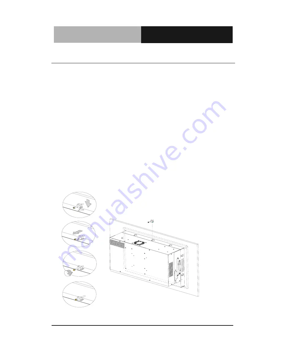
2.26 Panel Mount Kit Installation 

Some screw sets will come with the product for user to mount the 

monitor on the wall. See the steps below along with the illustration. 

Step 1:

 Bore the screw into the screw nut. 

Step 2:

 Locate the screw set into the hole around the monitor as 

the right illustration and pull it back to lock the screw set 

on the hole. 

Step 3:

 Turn the screw around to make it tight until it is closed to 

the wall.   

Step 4:

 Lock the monitor to the wall with the screw set which 

mean you’ve done a good job. 

1

2

3

4

P a n e l  M o u n tin g


Summary of Contents for APC-8122 Series

Page 1: ...Robust Panel PC A P C 8 1 2 2 APC 8122 Socket 478 based Intel Pentium 4 and Celeron Processors Robust Panel PC With 12 1 TFT LCD Two PCI expansion slots APC 8122 Manual 3rd Ed April 2007...

Page 2: ...his manual is intended to be accurate and reliable However the original manufacturer assumes no responsibility for its use or for any infringements upon the rights of third parties that may result fro...

Page 3: ...trademark of Microsoft Corporation RTL is a trademark of Realtek Semi Conductor Co Ltd C T is a trademark of Chips and Technologies Inc UMC is a trademark of United Microelectronics Corporation ITE is...

Page 4: ...APC 8122 Robust Panel PC 8 Panel mount brackets and screws 1 Easy stand 1 Waterproof sponge 1 Power Cord Optional 1 CD ROM Transfer board 1 CD ROM cable Optional 1 IDE cable Optional 1 CD ROM for manu...

Page 5: ...NOT COVER THE OPENINGS 8 Make sure the voltage of the power source is correct before connecting the equipment to the power outlet 9 Position the power cord so that people cannot step on it Do not pla...

Page 6: ...ll comply with relevant UL IEC standard e g UL 60950 for IT equipment and UL 2601 1 IEC 60601 series for medical electrical equipment In addition all such combinations systems shall comply with the st...

Page 7: ...Robust Panel PC A P C 8 1 2 2 vi Below Table for China RoHS Requirements AAEON Panel PC Workstation Pb Hg Cd Cr VI PBB PBDE O SJ T 11363 2006 X SJ T 11363 2006...

Page 8: ...3 List of Jumpers 2 4 2 4 List of Connectors 2 5 2 5 Setting Jumpers 2 6 2 6 Clear CMOS JP1 2 7 2 7 Audio Out Select JP2 2 7 2 8 COM2 Ring 5V 12V Selection JP3 2 7 2 9 COM2 RS 232 422 485 Select JP4...

Page 9: ...Easy Stand Installation 2 21 2 26 Panel Mount Kit Installation 2 22 2 27 Waterproof sponge Installation 2 23 Chapter 3 BIOS Installation 3 1 System Test and Initialization 3 2 3 2 Award BIOS Setup 3 3...

Page 10: ...1 2 2 ix 3 13 Save Exit Setup 3 7 3 14 Exit without saving 3 7 3 15 Limitations 3 7 Chapter 4 Driver Installation 4 1 Intel INF Update for Windows 9x XP Driver Installation 4 2 4 2 Intel 845G Graphics...

Page 11: ...Panel PC A P C 8 1 2 2 x 4 3 LAN Driver Installation 4 3 4 4 Realtek AC97 Codec Driver Installation 4 4 4 5 Card Reader Driver Installation 4 4 4 6 Touch Screen Driver Installation 4 4 4 7 Limitation...

Page 12: ...Robust Panel PC A P C 8 1 2 2 Chapter 1 General Information 1 1 General Chapter 1 Information...

Page 13: ...e point of information Kiosk and gaming markets Multi Function Pentium 4 Platform If you are looking for powerful multi media applications APC 8122 is the one APC 8122 integrates 12 1 color TFT LCD Di...

Page 14: ...800 x 600 LCD Socket 478 based Intel Pentium 4 and Celeron Processors FSB 400 533 MHz Anti vibration Disk Drive Bay for HDD Anti scratch Waterproof Aluminum Front Panel with USB Port has Certified IP...

Page 15: ...t panel CPU Socket 478 based Intel Pentium 4 and Celeron Processors FSB 400 533 MHz LCD CRT Controller Intel i845GV AGP 4 System Memory Support up to 1GB DDR SDRAM 200 266 333MHz OS Support Windows 20...

Page 16: ...ll AAEON s LCD products are manufactured with High precision technology However in all LCD panels there maybe a small number of defective pixels that do not change color This is a normal occurrence fo...

Page 17: ...Optional IO IO 3 Serial Ports 2 x RS 232 1 x RS 232 422 485 COM 4 is reserved for touchscreen 1 Parallel Port supports ECP EPP 1 PS 2 Mouse Port 1 PS 2 Keyboard Port 1 VGA Port Audio Mic in Line in Sp...

Page 18: ...dity 10 90 35 C non condensing Vibration Random operation 1 0G 5 500Hz Shock 15G peak acceleration 11 msec Duration EMC CE FCC Class B Dimension 16 x 12 22 x 2 56 407mm x 310 5mm x 65mm Carton Dimensi...

Page 19: ...rt with waterproof cover Wireless LAN Kit Optional 6 in 1 Card Reader CD ROM or DVD or Combo Parallel Port Power Connector Digital I O PS 2 Keyboard Mouse USB 2 0 COM 3 2 PCI Expansion Slots System Po...

Page 20: ...l PC A P C 8 1 2 2 Chapter 1 General Information 1 9 1 4 Dimension 366 00 291 00 255 00 18 00 18 00 249 00 140 00 9 00 330 00 150 00 8 00 18 00 18 00 CUTOUT SIZE 333 x 260 mm APC 8122 UNIT mm 180 00 1...

Page 21: ...Robust Panel PC A P C 8 1 2 2 Chapter 2 Hardware Installation 2 1 Hardware Installation Chapter 2...

Page 22: ...le the power is on because a sudden rush of power can damage sensitive electronic components Always ground yourself to remove any static charge before touching the board Modern electronic devices are...

Page 23: ...Robust Panel PC A P C 8 1 2 2 Chapter 2 Hardware Installation 2 3 2 2 Location of Connectors and Jumpers Component Side...

Page 24: ...low you to configure your system to suit your application The table below shows the function of each jumper in the board Jumpers Label Function JP1 Clear CMOS JP2 Audio Out Select JP3 COM2 Ring 5V 12V...

Page 25: ...ure your system to suit your application The table below shows the function of each connector in the board Connectors Label Function CN1 EIDE HDD Connector CN8 CN24 Fan Connector CN11 10 100Base Tx Et...

Page 26: ...em To close a jumper you connect the pins with the clip To open a jumper you remove the clip Sometimes a jumper will have three pins labeled 1 2 and 3 In this case you would connect either pins 1 and...

Page 27: ...power supply set the jumper back to Normal JP1 Function 1 2 Active Default 2 3 Clear 2 7 Audio Out Select JP2 JP2 Function 1 3 2 4 W O Amplifier Default 3 5 4 6 W Amplifier 2 8 COM2 Ring 5V 12V Selec...

Page 28: ...2 11 IDE Connector CN1 Pin Signal Pin Signal 1 IDE RESET 2 GND 3 DATA7 4 DATA8 5 DATA6 6 DATA9 7 DATA5 8 DATA10 9 DATA4 10 DATA11 11 DATA3 12 DATA12 13 DATA2 14 DATA13 15 DATA1 16 DATA14 17 DATA0 18...

Page 29: ...CN24 Pin Signal 1 GND 2 5V 3 FAN SPEED SENSE 2 13 10 100Base TX Ethernet Connector CN11 Pin Signal Pin Signal 1 TX 9 N C 2 TX 10 N C 3 RX 11 GND 4 N C 12 GND 5 N C 13 N C 6 RX 14 N C 7 N C 15 N C 8 N...

Page 30: ...EX 9 GND 10 MOTOR A 11 GND 12 DRIVE SELECT B 13 GND 14 DRIVE SELECT A 15 GND 16 MOTOR B 17 GND 18 DIR 19 GND 20 STEP 21 GND 22 WRITE DATA 23 GND 24 WRITE GATE 25 GND 26 TRACK 27 GND 28 WRITE PROTECT 2...

Page 31: ...D 19 ACK 20 GND 21 BUSY 22 GND 23 PE 24 GND 25 SELECT 26 N C 2 17 COM1 4 RS 232 422 485 Serial Port Connector CN16 5 1 9 6 Only COM 2 support Wake on Ring 5V 12V function COM 4 is reserved for touch s...

Page 32: ...in Signal 1 KB_DATA 2 KB_CLK 3 GND 4 5V 5 MS_DATA 6 MS_CLK 2 19 Digital I O Port Pin Signal I O Address Setting 1 Digital IN OUT 801H 2 Digital IN OUT 801H 3 Digital IN OUT 801H 4 Digital IN OUT 801H...

Page 33: ...41H 20 Digital IN OUT 841H 21 Digital IN OUT 841H 22 Digital IN OUT 841H 23 5V 24 5V 25 5V The pin definitions and registers mapping are illustrated below Address 801H 4 in 4 out Pin1 Pin2 Pin3 Pin4 P...

Page 34: ...n22 GPI 27 GPI 26 GPI 25 GPI 24 GPO 23 GPO 22 GPO 21 GPO 20 MSB LSB 8 in Pin13 Pin14 Pin15 Pin16 Pin19 Pin20 Pin21 Pin22 GPI 27 GPI 26 GPI 25 GPI 24 GPI 23 GPI 22 GPI 21 GPI 20 MSB LSB 8 out Pin13 Pin...

Page 35: ...SDA 16 N C 2 21 ATX Power Connector CN27 Pin Signal Pin Signal 1 3 3V 11 3 3V 2 3 3V 12 12V 3 GND 13 GND 4 5V 14 PS_ON 5 GND 15 GND 6 5V 16 GND 7 GND 17 GND 8 POWER OK 18 5V 9 5VSB 19 5V 10 12V 20 5V...

Page 36: ...ware Installation 2 16 2 23 HDD Installation In the following we will guide you how to install HDD Make sure that all parts are provided before you start the installation Step 1 Remove the back cover...

Page 37: ...Robust Panel PC A P C 8 1 2 2 Chapter 2 Hardware Installation 2 17 Step 3 Unlock the HDD module Step 4 Insert the IDE cable into HDD and fix the HDD on the bracket with screws...

Page 38: ...Robust Panel PC A P C 8 1 2 2 Chapter 2 Hardware Installation 2 18 Step 5 Fix the HDD module with screws as follow Step 6 Insert the IDE cable on the board...

Page 39: ...ROM Installation After you complete the HDD Installation we will guide you how to install CD ROM Please see the detail as follows Step 1 Insert CD ROM cable in the transfer board and plug the transfe...

Page 40: ...Robust Panel PC A P C 8 1 2 2 Chapter 2 Hardware Installation 2 20 Step 3 Push the CD ROM module into the board Step 4 Plug in CD ROM Cable as the indicated...

Page 41: ...tion 2 21 2 25 Easy Stand Installation There re two L shaped easy stands come with the product Refer to the following illustration to install it Fix the L shaped easy stands with the screws on both si...

Page 42: ...along with the illustration Step 1 Bore the screw into the screw nut Step 2 Locate the screw set into the hole around the monitor as the right illustration and pull it back to lock the screw set on t...

Page 43: ...tion 2 23 2 27 Waterproof sponge Installation The following illustration shows you how to lodge the waterproof sponge in the back of the monitor set Step 1 Lodge the Sponge in the back of the monitor...

Page 44: ...Robust Panel PC A P C 8 1 2 2 Chapter 3 BIOS Installation 3 1 Chapter BIOS 3 Installation...

Page 45: ...ong with the following instructions Press F1 to RESUME Write down the message and press the F1 key to continue the boot up sequence System configuration verification These routines check the current s...

Page 46: ...tery backed CMOS RAM so that it retains the Setup information when the power is turned off Entering setup Power on the computer and press Del immediately This will allow you to enter Setup Standard CM...

Page 47: ...down temperature for your system Frequency Voltage Control Use this menu to specify your settings for frequency voltage control Load CRT LCD Defaults Use this option to load the CRT LCD default settin...

Page 48: ...cturer s default values for the APC 8122 3 5 Advanced Chipset Features This sample screen contains the manufacturer s default values for the APC 8122 Attention 1 The LCD signal may be turned off autom...

Page 49: ...on dialog box with a message similar to Load CRT LCD Defaults or Load LCD Defaults Pressing one item loads the CRT LCD default or LCD default setting which allows the VGA displaying events on CRT and...

Page 50: ...s to what it finds as it checks the system This record is required for the system to operate 3 14 Exit without saving Selecting this option and pressing Enter allows you to exit the Setup program with...

Page 51: ...Robust Panel PC A P C 8 1 2 2 Chapter 4 Driver Installation 4 1 Chapter Driv 4er Installation...

Page 52: ...el LAN Driver Installation Step 5 Realtek AC97 codec Driver Installation Step 6 Card Reader Driver Installation Step 7 Touch screen Driver Installation USB 2 0 Drivers are available for download using...

Page 53: ...xe Please follow the steps in order to finish the process of installation 1 Click on Start button Settings Control Panel System 2 Select Device Manager under the Hardware category 3 Double click on th...

Page 54: ...ou 3 The system will install the driver automatically 4 6 Touch Screen Driver Installation 1 Double click on the Setup exe file 2 Follow the instructions the window shows you 3 The system will install...

Reviews: