background image

T o u c h   P a n e l   P C  

A H P - 1 0 8 1


Chapter 2 Quick Installation Guide 

2 - 2 


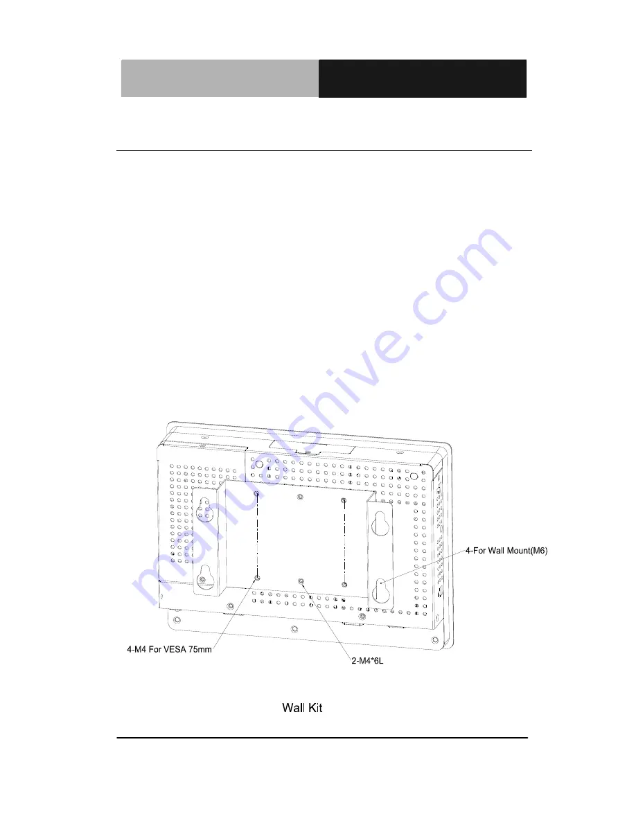
2.1 Panelmount Installation 

The display panel can be mounted into the wall. You will need the 

screws along with the mounting brackets, which be packed in the 

accessory box. Follow the steps below: 

Step 1: Place the operator panel into the wall. 

Step 2: Place the mounting brackets and bore the screw on it. 

Step 3: Screw mounting kits to fix the operator panel. 

Step 4: When the mounting set has been tightened, repeat the   

Steps above and tighten all mounting sets around the 

monitor until the monitor has been firmly mounted to 

the wall. 


Summary of Contents for AHP-1081

Page 1: ...Touch Panel PC A H P 1 0 8 1 AHP 1081 Intel Atom N270 1 6 GHz Processor Touch Panel PC With 8 4 TFT LCD AHP 1081 Manual 2nd Ed December 2010...

Page 2: ...is manual is intended to be accurate and reliable However the original manufacturer assumes no responsibility for its use or for any infringements upon the rights of third parties that may result from...

Page 3: ...rd is a trademark of Award Software International Inc Intel and Atom are trademarks of Intel Corporation Microsoft Windows is a registered trademark of Microsoft Corp IBM PC AT PS 2 and VGA are tradem...

Page 4: ...e sure that the following materials are enclosed z 1 AHP 1081 Touch Panel PC z 1 Phoenix Terminal Block z 1 Mounting bracket and screws z 1 CD ROM for manual in PDF format If any of these items should...

Page 5: ...NOT COVER THE OPENINGS 8 Make sure the voltage of the power source is correct before connecting the equipment to the power outlet 9 Position the power cord so that people cannot step on it Do not pla...

Page 6: ...MENT FCC This device complies with Part 15 FCC Rules Operation is subject to the following two conditions 1 this device may not cause harmful interference and 2 this device must accept any interferenc...

Page 7: ...Touch Panel PC A H P 1 0 8 1 vi Below Table for China RoHS Requirements AAEON Panel PC Workstation Pb Hg Cd Cr VI PBB PBDE O SJ T 11363 2006 X SJ T 11363 2006...

Page 8: ...Dimension 1 6 Chapter 2 Hardware Installation 2 1 Panelmount Installation 2 2 2 2 COM 1 2 RS 232 422 485 Serial Port Connector 2 3 2 3 CompactFlash Installation 2 4 2 4 Hard Disk Drive Installation 2...

Page 9: ...Touch Panel PC A H P 1 0 8 1 Chapter 1 General Information 1 1 General Chapter 1 Information...

Page 10: ...puter In addition its fit anywhere design makes it very flexible and able to be used in many different kinds of installations It can be wall mounted panel mounted or DIN Rail mounted For system integr...

Page 11: ...LCD CRT Controller Intel 945GSE Integrated z I O Port USB2 0 x 2 RS 232 x 1 RS 232 422 485 x 1 LAN x 2 VGA x 1 Power input x 1 Power button x 1 z Storage Disk Drive Type2 CompactFlash slot x 1 Easy to...

Page 12: ...x 195mm x 250mm z Net Weight 3 3 lb 1 5 kg z Gross Weight 4 4 lb 2 kg Environmental z Operating Temperature 32 o F 122 o F 0 o C 50 o C z Storage Temperature 4 o F 158 o F 20 o C 70 o C z Operating H...

Page 13: ...nsumption 7 44W z Response Time msec 10 z Interface Single channel LVDS z Luminance cd m 2 450 nits z Contrast Ratio 600 1 z Viewing Angle 160 o H x 140 o V z Backlight MTBF Hours 50 000 Touch Screen...

Page 14: ...Touch Panel PC A H P 1 0 8 1 Chapter 1 General Information 1 6 1 3 Dimension 75 0 75 0 40 9 175 9 237 9 48 8 146 4 3 8 245 0 183 0 AHP 1081 Cut Out 241 180mm Untis mm...

Page 15: ...Touch Panel PC A H P 1 0 8 1 Chapter 2 Quick Installation Guide 2 1 Hardware Installation Chapter 2...

Page 16: ...ets which be packed in the accessory box Follow the steps below Step 1 Place the operator panel into the wall Step 2 Place the mounting brackets and bore the screw on it Step 3 Screw mounting kits to...

Page 17: ...rt Connector COM1 D sub 9 male 5 4 2 1 9 8 6 7 Pin Signal Pin Signal 1 DCD 2 RXD 3 TXD 4 DTR 5 GND 6 DSR 7 RTS 8 CTS 9 RI COM2 RS 232 422 485 D sub 9 male 5 4 2 1 9 8 6 7 Pin Signal Pin Signal 1 DCD 4...

Page 18: ...nel PC A H P 1 0 8 1 Chapter 2 Quick Installation Guide 2 4 2 3 CompactFlash Installation Step 1 Loose the screw of cover to open the CompactFlash Slot Step 2 Insert the CompactFlash to the CompactFla...

Page 19: ...PC A H P 1 0 8 1 Chapter 2 Quick Installation Guide 2 5 2 4 Hard Disk Drive Installation Step 1 Loose the three screws of the cover to get the Hard Disk Drive HDD bracket Step 2 Insert the HDD to the...

Page 20: ...Touch Panel PC A H P 1 0 8 1 Chapter 2 Quick Installation Guide 2 6 Step 3 Fasten the four screws to fasten the HDD and the HDD bracket Step 4 Connect the SATA cable to the HDD...

Page 21: ...Touch Panel PC A H P 1 0 8 1 Chapter 3 Windows XP Embedded Installation 3 1 Windows XP Chapter 3 Embedded Installation...

Page 22: ...XP Embedded image in your CF Disk After Touchscreen calibration you can start to use AHP 1081 Request for different features of Windows XP Embedded Please refer to AAEON Windows XP Embedded Installati...

Page 23: ...Touch Panel PC A H P 1 0 8 1 Chapter 4 Driver Installation 4 1 Driver Chapter 4 Installation...

Page 24: ...ins all drivers and utilities that meet your needs Follow the sequence below to install the drivers Step 1 Install INF Driver Step 2 Install VGA Driver Step 3 Install LAN Driver Step 4 Install Audio D...

Page 25: ...VGA Driver 1 Click on the Step 2 Intel Graphics Media Accelerator Driver folder and double click on the Setup exe 2 Follow the instructions that the window shows 3 The system will help you install th...

Page 26: ...em will help you install the driver automatically Step 5 Install Touch Panel Driver 1 Click on the Step 5 Touch Panel Driver folder and double click on the Setup exe 2 Follow the instructions that the...

Reviews: