background image

4.3 Reverse polarity protection: charger will not turn on if the battery pack is connected 
backwards (or 
less than 5V). 
4.4 A switch on the charger marked “Override” is used to select either external or internal 
controlled charging. 
    Override Off @ Use with EMS system, either CAN or digital input 
    Override On @ Charger program based on pack voltage only (recommended for testing 
                          purposes only, do not use for normal charging).


4.5 When external control is selected and a CAN signal is used, if any cell reaches the recharge 
set point (default 3.7V as signaled by the EMS) the charger will automatically enter the final 
recharge cycles. 
4.6 Recharge cycles. When the EMS detects any cell has reached the recharge set point (default 
3.7V) or above, the charger reduces the charge current to zero amps for five minutes to allow 
the EMS to balance the battery pack. The charge will resume after five minutes at half the 
previous charge current and will again charge until it receives a signal from the EMS that a cell 
has reached the recharge set point. These recharge cycles continue until the charging current 
reaches the minimum charging current to complete the charging process. 
4.7 Digital alarm input: 
               0.0V - 2.0V: Charging stopped 
               2.5V - 12.0V: Enable charging or resume charging 
4.8 When both CAN and the digital control signals are available the charger is controlled by the 
CAN communication signal. 


5. Connections 

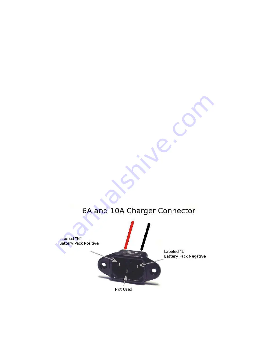
5.1 IEC Connector 
For EMC chargers which output 10A or less the charger comes with an IEC type connector for 
the output. The connections to the battery pack are made as follows: 


Summary of Contents for EMC series

Page 1: ...ls LiFePO4 Battery Pack 110V only Standard Female plug AA Portable Power Corp http www batteryspace com Address 860 S 19th St Unit A Richmond CA 94804 Tel 510 525 2328 Fax 510 439 2808 Email Sales bat...

Page 2: ...used in electric vehicle applications The EMC series chargers are designed to work seamlessly with EMS through the CAN interface or digital input for safe battery charging Standard safety features inc...

Page 3: ...n Reverse polarity or low voltage Red light blinking 20 light on Charger over heating Red light blinking 40 light on Ambient temperature too high Red light blinking 60 light on Charging time out Red l...

Page 4: ...e recharge set point default 3 7V or above the charger reduces the charge current to zero amps for five minutes to allow the EMS to balance the battery pack The charge will resume after five minutes a...

Page 5: ...rface The other two wires are labeled 12V and 12V these wires are the digital input used to control the charger from the EMS CPU Connect the 12V to the 0V connection on the EMS CPU and the 12V to the...

Page 6: ...ication connection connect the CANH CANL and CAN GND to the matching connection on the CAN connection on the EMS CPU The white connector may be cut off of the cable however note which wires are which...

Page 7: ...AN communication and the digital inputs are connected CAN communications will take priority over the digital input for charge control CAN communications requires the optional CAN board be installed on...

Page 8: ...A BMS system must be used during the charging process either through CAN communication or through the digital alarm input to prevent over charging 7 Troubleshooting The charger must be installed in a...

Page 9: ...If the fuse is blown replace with an equivalent size fuse of the same voltage and amperage rating If the charger finishes charging too early make sure that the connection from the charge to the batter...

Reviews: