10
AV500HD
English
1
Item
Illustration
Comments
HDMI
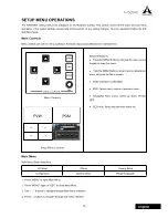
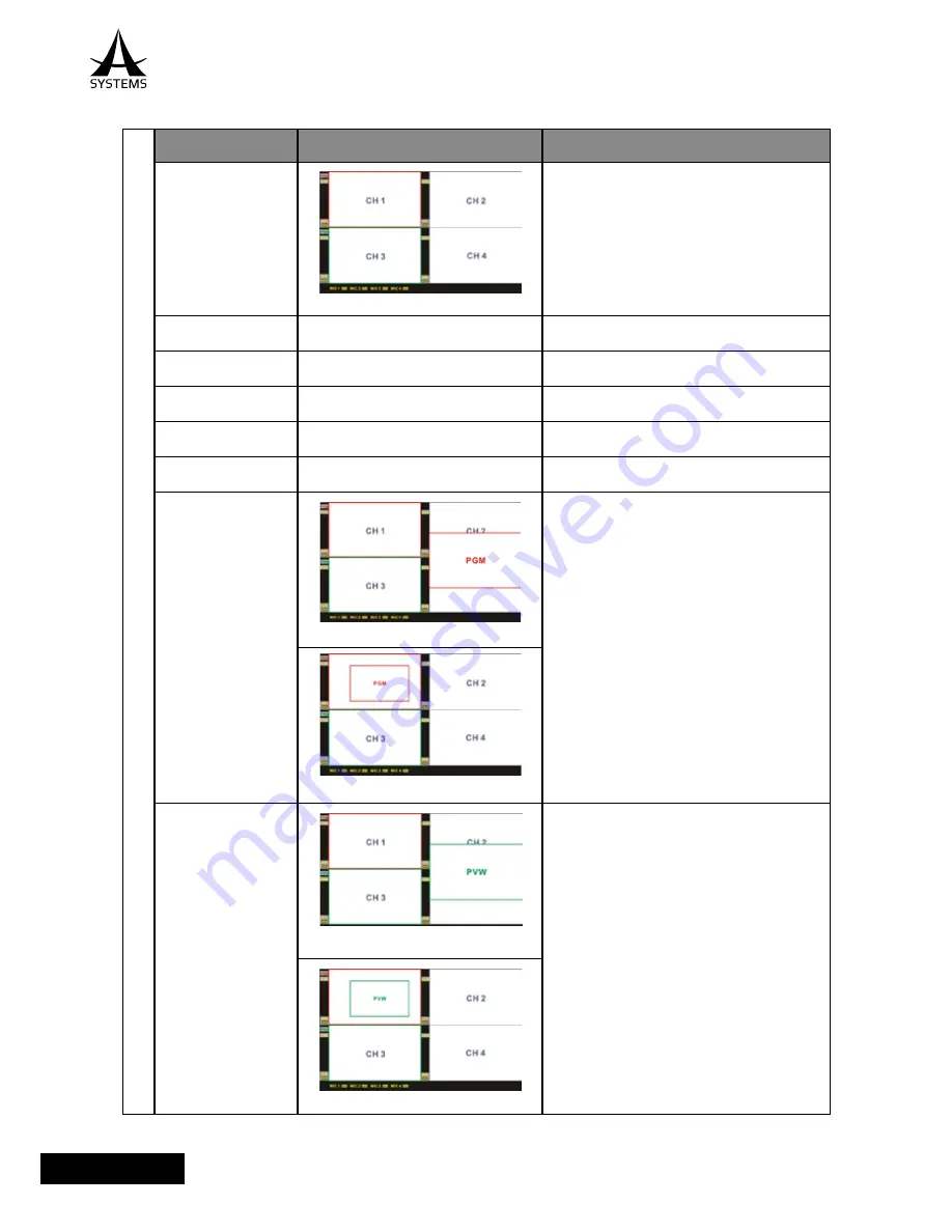
Fig. 1-1 Main Multiview Screen
Multiview Screen
a. PGM Label
Current PGM channel; red frame around PGM multiview
screen.
b. PVW Label
Current PVW channel; green frame around PVW
multiview screen.
c. CH Label
Crosspoint channel label
d. Audio label&meter
Current audio source and label
e. MIC label& meter
MIC inputs are not tied to channel; it will be directly
mixed into PGM.
f. PGM Out Display
Fig. 1-1 Main Multiview Screen
1. Double tap on PGM multiview screen will open PGM
out screen (Default starting position at right center);
PGM Out has red frame.
2. When PGM is open; use joystick to place PGM out
location.
3. Use Size knob to adjust PGM Out screen size.
4. Double tap on PGM Out screen area to close PGM
Out.
Note: PGM Out and PVW Out will share the same
positon and size data; when PGM Out or PVW Out is
closed, the last position and size data will be retained
(Until it is reset).
Fig 1f-2 PGM Out at custom location and size.
g. PVW Out Display
Fig. 1g-1 PGM Out starting location
1. Double tap on PVW multiview screen will open PVW
Out screen (Default starting position at right center);
PVW Out has green frame.
2. When PVW is open; use joystick to place PVW out
location.
3. Use Size knob to adjust PVW Out screen size.
4. Double tap on PVW Out screen area to close PVW
Out.
Note: PGM Out and PVW Out will share the same
positon and size data; when PGM Out or PVW Out is
closed, the last position and size data will be retained
(Until it is reset).
Fig 1g-2 PGM Out at custom location and size.
MONITOR SELECT


