background image

9

AV50

English

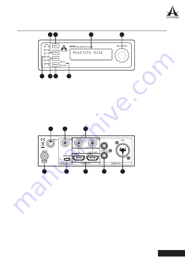
AV50 FRONT AND REAR PANELS

1.  SEL/ENTER Control: 

Rotate to scroll through onscreen options. Push to confirm.

2.  LCD Screen:

 Two lines of data will be displayed here. Use the SEL/ENTER control to adjust. 

3.  INPUT Button: 

Push to toggle input between SDI and HDMI in (LED indicates current input source).

4.  VIDEO Button:

 Opens up the video transition menu.

5.  AUDIO Button:

 Push to open up advanced audio options.

6.  MENU Button:

 Push this button to access the AV50’s main menu.

7.  LEVEL METER:

 This is a stereo audio level meter. Audio should sit around 0dB for best results.

8.  SDI/HDMI Indicators:

 These LEDs will light up when the corresponding source is active.

1

3

4

5

2

6

7

9

10

11

13

12

14

15

16

8

1

3

4

5

2

6

7

9

10

11

13

12

14

15

16

8

9.  DC IN:

 This BNC connector is for connection of the included power adapter.

10. TALLY  Connector:

 Connect the Tally connector to your camera to send a tally signal when active.

11. SDI Output: 

This is the main program output.

12. WEBCAM: 

This USB-C connector was for connection of a Windows or Mac computer. The AV50 is 

recognized and works as a virtual webcam within applications that are compatible with such devices.

13. SDI INPUT/LOOP OUT:

 The “IN” 3G-SDI connector is for connection of an appropriate video source. 

The LOOP OUT can be connected to a suitable display or input device.

14. HDMI INPUT/LOOP OUT:

 These HDMI 1.1 connectors are appropriate for connection of suitable 

HDMI-enabled devices. The “IN” is for video sources and the “LOOP OUT” is for displays or other 

input devices.

15. RCA  Inputs:

 These stereo RCA inputs are ideal for line-level audio inputs.

16. Mic Input:

 This mono Combo input connector is perfect for Microphones and accepts both XLR and 

¼” phone jack connectors. 

Summary of Contents for AV50

Page 1: ...User s Manual High Definition 2 Channel Web Video Switcher Converter AV50...

Page 2: ...the apparatus has been damaged in any way such as power supply cord or plug is damaged liquid has been spilled or objects have fallen into the apparatus has been exposed to rain or moisture does not...

Page 3: ...ction 4 Connection Diagrams 5 Installation Precautions 7 Operating Precautions 8 AV50 Front and Rear Panels 9 Settings 10 Audio 10 Video 10 Setup Menu 11 Firmware Upgrade 12 Specifications 13 TABLE OF...

Page 4: ...ore operating and exploring the possibilities of the AV50 it is highly recommended that you carefully read through the Safety and Precaution sections first for safe operation while avoiding hazardous...

Page 5: ...eplacements AV50 Power Adapter Owner s Manual User s Manual High Definition 2 Channel Web Streaming Converter A V 5 0 POWER UP As noted above Asystems have included a DC power adapter for powering the...

Page 6: ...e injected into the AV50 The Combo inputs accept XLR connectors perfect for professional microphones and phone jack inputs ideal for line level devices While this is a mono input any signal will be se...

Page 7: ...as a source display for each The program output is sent for broadcasting An analog mixer is connected to the stereo Line In connectors while a separate microphone is connected directly to the AV50 Fin...

Page 8: ...example the video mixer s program output is connected directly to the AV50 s video input then looped out for broadcast The AV50 s only job in this example is to take the broadcast signal and stream i...

Page 9: ...is unit is designed for indoor use only Install the unit on a sufficiently strong stable and level surface for use Ensure a space of at least 100 mm 4 inches around the unit While the AV50 won t run h...

Page 10: ...ce Wipe the product using a dry cloth to remove stubborn dirt dip a cloth into a diluted solution of kitchen detergent neutral wring it out well and wipe the product gently Then after wiping the produ...

Page 11: ...connector is for connection of the included power adapter 10 TALLY Connector Connect the Tally connector to your camera to send a tally signal when active 11 SDI Output This is the main program outpu...

Page 12: ...inputs also offer a Follow option that can be turned on and off When either input is set to Follow the audio for that input will be sent to the main program output when that input is selected Embeddin...

Page 13: ...onds of inactivity Use the recall option to restore the AV50 to the factory default settings Select Y to confirm recall of default settings This option allows users to determine where to set the Tally...

Page 14: ...R to confirm 3 Available firmware files will be displayed on screen use the SEL ENTER control to scroll through firmware files and push ENTER to confirm 4 Updating progress will be displayed on screen...

Page 15: ...ut SDI Loop Out 3G SDI PGM Out 1080p60 max same as input HDMI Loop Out 1080p60 max same as input USB 3 0 USB C Webcam Out fixed at 1080p60 Audio SDI HDMI Embedded Audio Microphone In Combo Input XLR T...

Page 16: ...www asystems sys com...

Reviews: