6
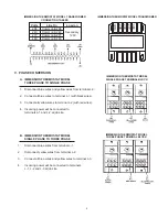
C. SURFACE THERMOSTAT MODEL
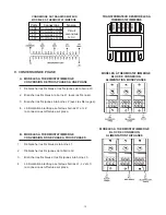
THREE PHASE TO SINGLE PHASE
1. Disconnect blue wires from terminal L-2.
2. Connect all blue wires to terminal L-1
(with black wires).
3. Disconnect all red wires from terminal L-3.
4. Connect all red wires to terminal L-2 (with yellow wires).
5. Incoming power will be connected to
terminals L-1 and L-2 at job site.
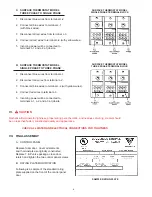
D. SURFACE THERMOSTAT MODEL
SINGLE PHASE TO THREE PHASE
1. Disconnect blue wires from terminal L-1
2. Disconnect red wires from terminal L-2.
3. Connect all blue wires to terminal L-2 (with yellow wires).
4. Connect red wires to terminal L-3.
5. Incoming power will be connected to
terminals L-1, L-2 and L-3 at job site.
VI.
CAUTION
Recheck all terminals for tightness, proper wiring per schematic, and neatness of wiring, Heater should
be no less than factory constructed quality and appearance.
CHECK ALL WATER AND ELECTRICAL CONNECTIONS FOR TIGHTNESS
VII. FINAL ASSEMBLY
A. CONTROL PANEL
Replace foam door. Cover all elements
and thermostats as originally constructed.
Replace T & P valve package, close door,
relatch and tighten the two control panel screws.
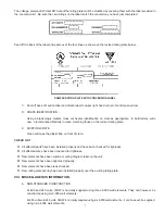
B. RATING PLATE MODIFICATION
Following is a sample of the standard rating
plate supplied on the front of the control panel
door.
SURFACE THERMOSTAT MODEL
SINGLE PHASE TERMINAL BLOCK
SURFACE THERMOSTAT MODEL
THREE PHASE TERMINAL BLOCK
SAMPLE RATING PLATE


