32
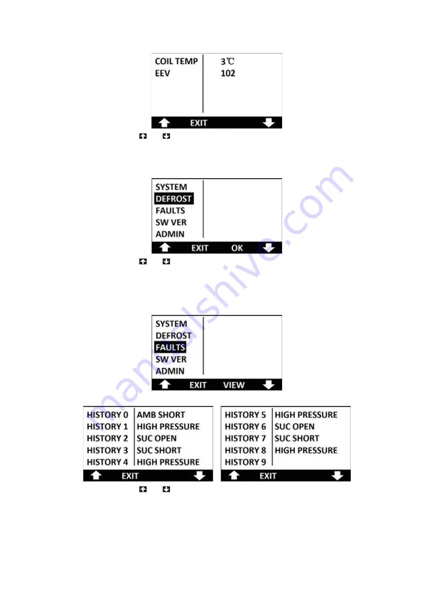
Figure 5.35
Press the button of
or
to select the sub menu of SYSTEM on the maintenance
menu as illustrated in figure 5.36. Press the button of OK on the interface, the unit will perform
manual defrost.
Figure 5.36
Press the button of
or
to select the sub menu of FAULTS on the maintenance
menu interface as illustrated in figure 5.37. Press the button of VIEW to inspect the faults
record. Compare with CAHP80/120 units, CAHP120C unit can record ten faults as illustrated
in figure 5.38 and figure 5.39.
Figure 5.37
Figure 5.38 Figure 5.39
Press the button of
or
to select the sub menu of SW VER on the maintenance
menu as illustrated in figure 5.40. Press the button of VIEW to inspect the software versions
and check codes of main control board and display board illustrated in figure 5.41. Comparing
with the released check codes can confirm if the software is disturbed or if it is the latest
version. Press the button of EXIT to return to the last menu interface.
The version numbers will change once the software is updated. A.O. Smith reserves the
Summary of Contents for CAHP-120 Series
Page 1: ...R...
Page 42: ...41 8 APPENDIX 8 1 CAHP 80I 120I Wiring Diagram...
Page 43: ...42 8 2 CAHP 80T 120T Wiring Diagram...
Page 44: ...43 8 3 CAHP120C 3KW Wiring Diagram...
Page 45: ...44 8 4 CAHP120C 4KW 5KW 6KW Wiring Diagram...
Page 46: ...R...


